Eureka AIR delivers breakthrough ideas for toughest innovation challenges, trusted by R&D personnel around the world.

A wind-driven direct-drive generator that adjusts the windward angle of the sail according to the wind direction

A windward angle and generator technology, which is applied to wind turbines, wind turbines, and combinations of wind turbines at right angles to the wind direction, can solve problems such as the inability to adjust the load, the low utilization rate of wind power, and the inability to combine motors, so as to increase wind energy. Utilization, low cost, effect of increasing mechanical life

Active Publication Date: 2019-08-20
KEDE NUMERICAL CONTROL CO LTD
View PDF6 Cites 0 Cited by
  • Summary
  • Abstract
  • Description
  • Claims
  • Application Information

AI Technical Summary

Problems solved by technology

However, there is also the problem that the load cannot be adjusted. After the generator is designed, the motor cannot be combined in any way according to the local maximum and minimum wind speed.
In addition, the utilization rate of wind power is low and the service life of rotating parts such as bearings is low.

Method used


Image

  • A wind-driven direct-drive generator that adjusts the windward angle of the sail according to the wind direction
  • A wind-driven direct-drive generator that adjusts the windward angle of the sail according to the wind direction
  • A wind-driven direct-drive generator that adjusts the windward angle of the sail according to the wind direction

Examples


Embodiment 1

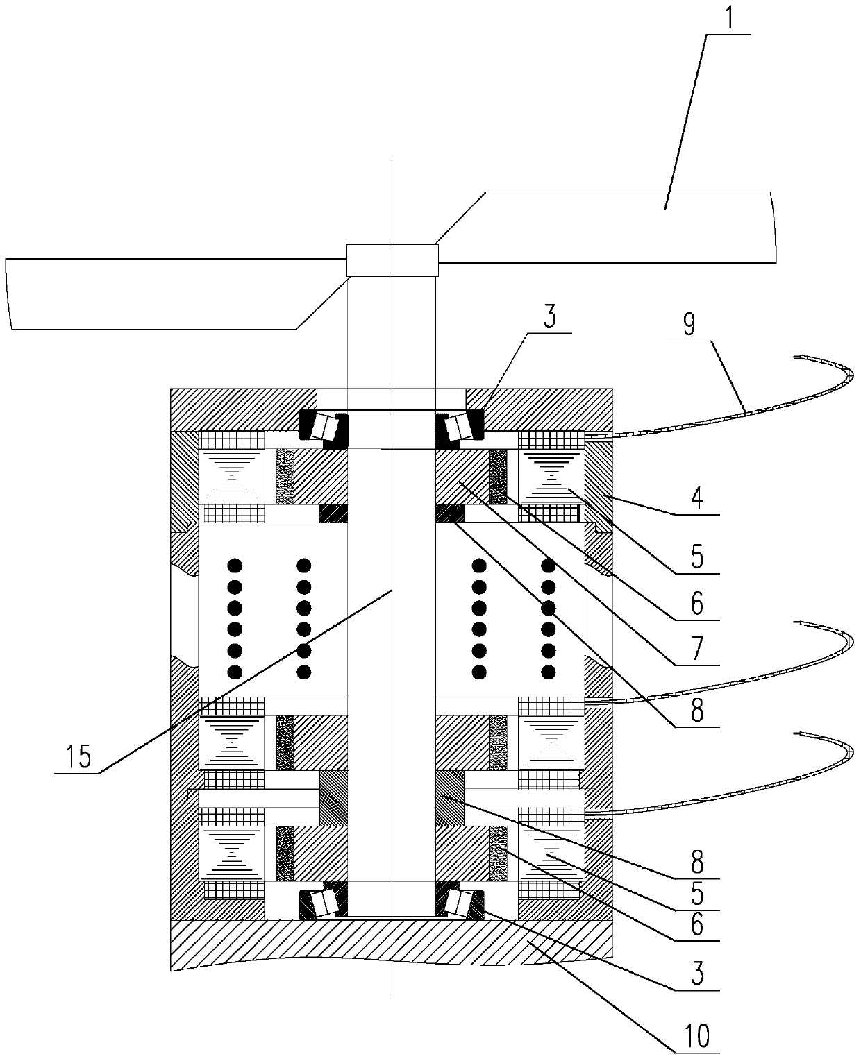
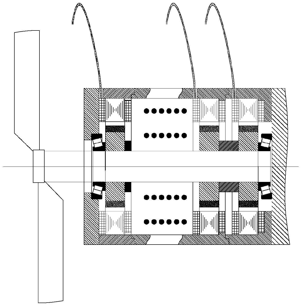
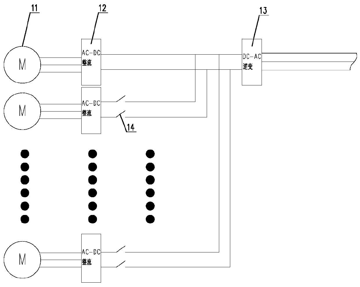
[0041] Such as figure 1 and image 3 As shown, the motor rotor of the generator unit includes: a rotor yoke 7 and a permanent magnet 6 ; the rotor yoke 7 is fixed on the power input shaft 15 , and the permanent magnet 6 is fixed on the rotor yoke 7 . A rotor spacer 8 is arranged between two adjacent generator units, and the rotor spacer 8 is arranged between two adjacent generator units and fixed on the power input shaft 15 . The motor stator 5 is connected with a motor lead wire 9 , and the motor lead wire 9 is drawn out through a through hole on the motor housing 4 and connected to an AC-DC rectifier 12 . The output power of the generator unit is transmitted to the AC-DC rectifier 12; the output terminal of the AC-DC rectifier 12 of each generator unit is connected in parallel to the input terminal of the DC-AC inverter 13, and passes through the DC-AC inverter 13 Output after inversion, or increase to 10KV or higher output through a power frequency transformer.

Embodiment 2

[0043] Such as Figure 4 As shown, the sail shaft 1.1 and the power input shaft 15 can be fixedly connected when they are designed separately, or they can be set as one. The generator also includes a support beam 1.6, the support beam 1.6 is used to support the sail shaft 1.1, and the support beam 1.6 is connected to the sail shaft 1.1 through the sail top layer bearing 1.7;

Embodiment 3

[0045] Such as Figure 4 As shown, the angle adjustment mechanism 1.5 includes a servo motor, a reducer and a moment arm lever connected to the self-adaptive windward blade 1.3, which is used to automatically adjust the angle of each self-adaptive windward blade 1.3 through the magnitude of the moment of the moment arm In this technical solution, the servo motor is used as the control power, and the collection of wind direction can be analyzed and controlled by setting sensors on the sail structure, or combining the wind direction and wind force in the weather forecast of the local meteorological bureau.


PUM


Abstract

The invention discloses a wind power direct driving power generator capable of changing a windward angle of a sail according to wind direction. The wind power direct driving power generator comprises a sail and a vertical shaft direct driving power generator in coaxial driving with the sail, wherein the sail comprises a sail shaft, a plurality of sail cross beams and self-response windward paddles corresponding to the number of the sail cross beams; the sail cross beams are fixed on the sail shaft; each self-response windward paddle ensures the windward transmission of a single-direction rotation torque through an angle regulating mechanism; the vertical shaft direct driving power generator is a power generator unit set formed by more than one power generator unit; in addition, a motor rotor of each power generator unit is fixed on a power input shaft of the vertical shaft direct diving power generator. By using the wind power direct driving power generator utilizing the technical scheme, the direct driving type power generation is used; meanwhile, the self-response windward paddles ensure the real-time wind direction facing through the angle regulating mechanism; the wind energy is utilized to the maximum degree; the design of the multi-stage coaxial driving power generation is used through being compared with the vertical shaft direct driving power generator; the power generating load controllability is realized; the stable power generation in the low-speed state can be further realized.

Description

technical field [0001] The invention relates to a wind power generator, in particular to a wind power direct drive generator which can automatically respond to change the windward angle of the sail according to the wind direction. Background technique [0002] Wind turbines use wind power to drive windmill blades to rotate, and then increase the speed of rotation through a speed increaser to drive the generator to generate electricity. Although the speed increaser ensures the reliable power generation of the wind turbine, it also brings: ①The overall volume of the generator is large, ②High cost, ③Low reliability, ④High noise of the speed-up mechanism, ⑤Because of multi-level speed-up , Increased the number of mechanical transmission stages, so the efficiency is low, and ⑥ installation is complicated. Although a multi-motor combined power generation was developed later, the number of stages of the speed reducer was reduced while increasing the power generation. However, the...

Claims


Application Information

Patent Timeline
Patent Type & Authority Patents(China)
IPC IPC(8): F03D9/25F03D3/06F03D7/06F03D15/20H02K7/18
Inventor 于德海王雪李东明杨金明姜贺何毅迟宁于勇
Owner KEDE NUMERICAL CONTROL CO LTD
Why Eureka
Eureka Blog
Learn More