Method for unfolding multi-honeycomb sandwich structure member upper skin paving layer

A technology of honeycomb interlayer and structural parts, which is applied in special data processing applications, instruments, electrical digital data processing, etc. It can solve the problems of lower production efficiency, uncurable laying methods, and poor laying effect, so as to improve product quality. Stability, skin unfolding efficiency and accuracy improvement, and the effect of reducing manufacturing difficulty

Inactive Publication Date: 2016-06-08
JIANGXI CHANGHE AVIATION IND
View PDF3 Cites 4 Cited by
  • Summary
  • Abstract
  • Description
  • Claims
  • Application Information

AI Technical Summary

Problems solved by technology

[0004] From the actual analysis and development process, it is found that for the upper skin of the multi-honeycomb sandwich structure, because its paving surface is an indivisible multi-curved surface, when using software to analyze the paving properties of the skin, regardless of the paving origin If it is set at any position on the paving surface, the paving effect will be poor in areas other than the origin of the paving, and it cannot be used for actual paving after unfolding
Therefore, in order to make the layup go smoothly, the prepreg pieces formed by blanking are usually larger than the sub-layups that are analyzed and unfolded using software, and the layup operator performs the cutting and block operations by himself. This method It will cause the strength of the part to decrease due to improper notch, the layering method cannot be cured, and the stability of product quality cannot be guaranteed. On the other hand, materials are wasted and production efficiency is reduced

Method used


Image

  • Method for unfolding multi-honeycomb sandwich structure member upper skin paving layer
  • Method for unfolding multi-honeycomb sandwich structure member upper skin paving layer
  • Method for unfolding multi-honeycomb sandwich structure member upper skin paving layer

Examples


Embodiment Construction

[0018] The specific implementation manner of the present invention will be described in further detail below in conjunction with the accompanying drawings.

[0019] Referring to the accompanying drawings, a method for unfolding skin layup on a multi-honeycomb sandwich structure is characterized in that it comprises the following steps:

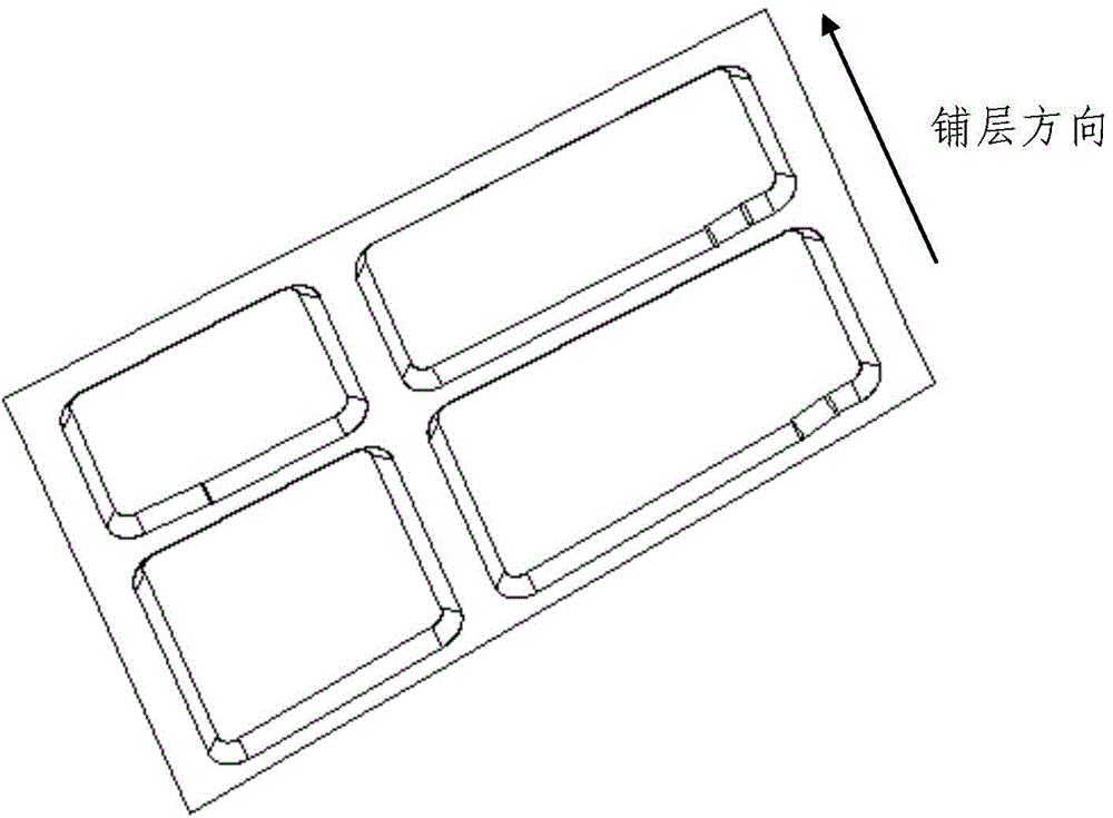
[0020] Step 1, make the paving surface of the skin on the multi-honeycomb sandwich structure in the human-computer interaction interface, see figure 1 ;

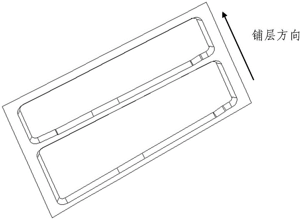
[0021] Step 2: On the human-computer interaction interface, fill up the non-honeycomb area parallel to the laying direction along the layering direction, and obtain the simulated surface of the skin on the multi-honeycomb sandwich structure, see figure 2 ;

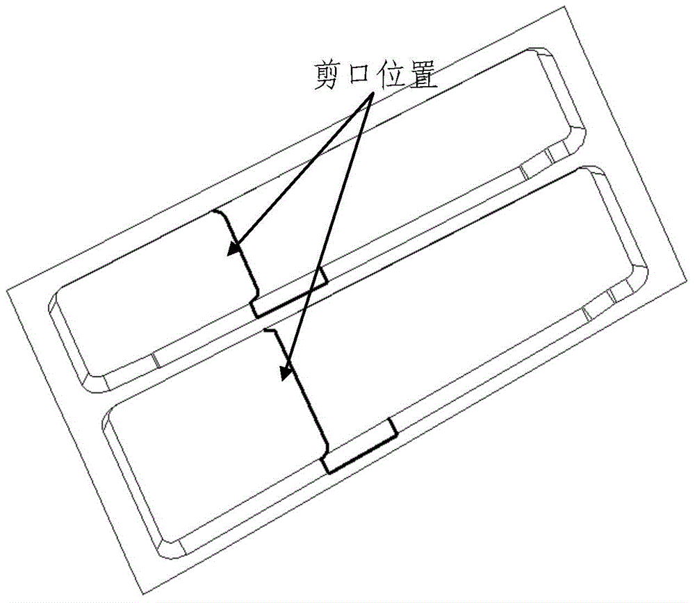
[0022] Step 3: Use the software to analyze the layup properties of the simulated surface of the composite component. After the analysis, spread the layup on the simulated surface to form the layup data of the upper skin. See Figure ...


PUM


Abstract

The invention provides a method for unfolding a multi-honeycomb sandwich structure member upper skin layer. The method includes the following steps: a first step, making a paving surface of a multi-honeycomb sandwich structure member upper skin in a human-computer interaction interface; a second step, filling up honeycomb-free zones parallel to a paving layer direction in the paving layer direction in the human-computer interaction interface to obtain a simulation surface of the multi-honeycomb sandwich structure member upper skin; a third step, using software to perform paving property analysis on the simulation surface of a composite material member, and then unfolding the paving layer on the simulation surface to form upper skin paving layer unfolding data; a forth step, using software to perform reasonable shearing on the paving layer on the paving surface and to make an outline of a patch cutting piece to form shearing position data and patch plane unfolding data; and a fifth step, inputting the upper skin paving layer unfolding data and the patch plane unfolding data into numerical control blanking data, inputting the shearing position data into laser projection data to complete unfolding of the multi-honeycomb sandwich structure member upper skin.

Description

technical field [0001] The invention belongs to the field of resin-based composite material component manufacturing, and relates to a method for deploying an upper skin of a multi-honeycomb sandwich structure. Background technique [0002] Due to its many advantages, dry-formed resin-based composite materials have been widely used in aerospace primary and secondary load-bearing structures. Its components are different from ordinary single-material parts. Generally, it is mainly composed of various grades of prepregs that are stacked layer by layer in the specified order, direction, and size. The layup position, layup direction and layup angle of each layer of prepreg in the component must meet the requirements. [0003] Use the digital design and manufacturing software of composite materials (such as FIBERSIM, CPD module in CATIA, etc.) to analyze the layup performance of the prepreg layup of composite material components, and through reasonable notches, the prepreg on each...

Claims


Application Information

Patent Timeline
Patent Type & Authority Applications(China)
IPC IPC(8): G06F17/50
Inventor 易卫冯汉斌张军文徐大鹏陶燕温菡袁琦王强余敏洋朱志强赖宝辉彭艳琴闵捷
Owner JIANGXI CHANGHE AVIATION IND
Why Eureka
Try Eureka