
RCS reduction method for phased-array antenna

A phased array antenna and array element technology, which is applied to antenna combinations, antennas, antenna arrays and other directions with different interactions, to achieve the effect of easy design, easy implementation, and reduced RCS

Active Publication Date: 2016-06-08
UNIV OF ELECTRONICS SCI & TECH OF CHINA
View PDF0 Cites 29 Cited by
  • Summary
  • Abstract
  • Description
  • Claims
  • Application Information

AI Technical Summary

Problems solved by technology

However, there are currently very limited reports on how to compromise between the radiation and scattering performance of the array, and how to integrate various RCS control technologies.

Method used


Image

  • RCS reduction method for phased-array antenna
  • RCS reduction method for phased-array antenna
  • RCS reduction method for phased-array antenna

Examples


Embodiment Construction

[0027] The present invention is described in detail below in conjunction with accompanying drawing

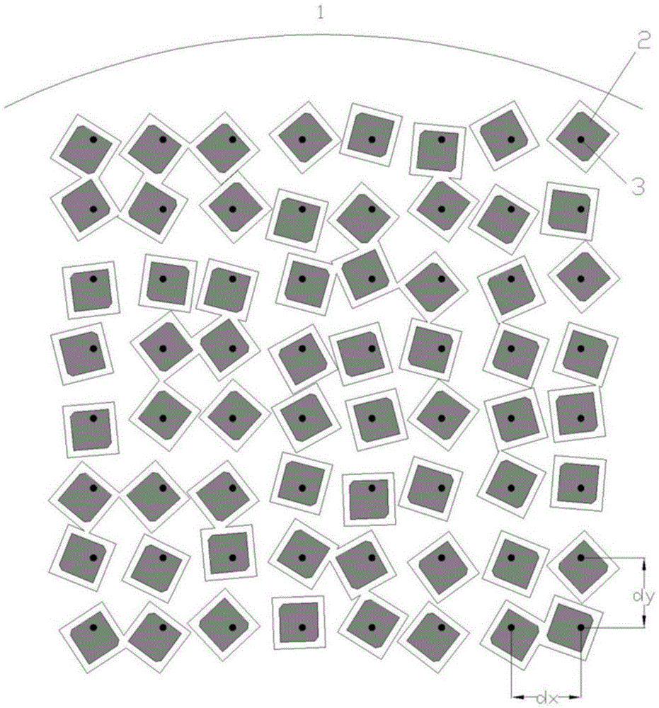
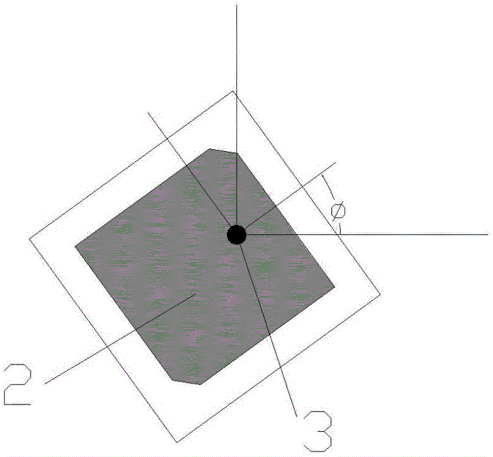
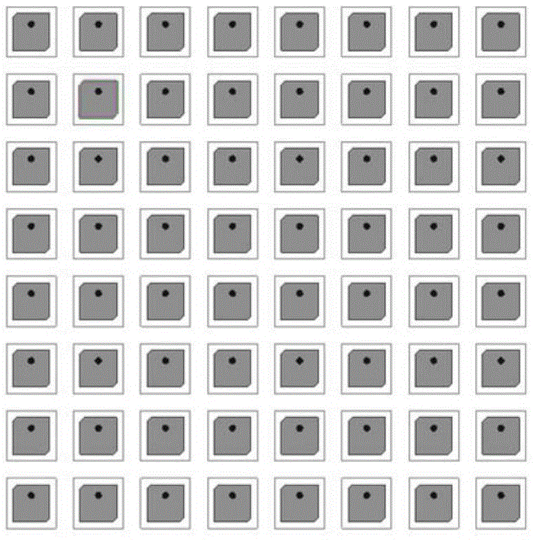
[0028] Such as figure 1 , figure 2 As shown, taking the circularly polarized microstrip antenna as an example, the antenna array 1 is composed of N circularly polarized microstrip antenna units 2, where N is the number of array elements. Of course, it is not limited to figure 1 As shown in the 8x8 array elements, the feed points 3 of the microstrip antenna unit 2 are regularly arranged in a rectangular grid, and the distances between the feed points 3 in the x and y directions are dx and dy respectively, The microstrip antenna unit 2 is randomly rotated by an angle φ around the feeding point 3 .

[0029] Further, the random rotation is in pairs. Specifically, the array elements are randomly divided into two groups, each group has N / 2 array elements, and random rotation is performed on each array element in the first group of array elements. Rotation, and the rotation angle ...


PUM


Abstract

The invention relates to the field of microwave antenna array design, and in particular relates to a RCS reduction method for a phased-array antenna. The method mainly comprises the steps of: assuming that the phased-array antenna comprises N array elements and then there are N feeding points correspondingly, and regularly arranging the N feeding points in a rectangular grid shape; and then rotating each array element by a random angle around the feeding point of the array element. The RCS reduction method for the phased-array antenna has advantages that the array RCS can be reduced greatly under the condition that the loss of the array radiance property is basically avoided; the RCS reduction can be realized just by the random rotation of the array elements; compared with traditional measurements such as structure forming and antenna housing loading, the design is easier, the realization is easier, the process is easier and the cost is lower; in addition, the array elements rotate around the feeding points, and the array elements retains the regular arrangement structure of the feeding points although the array elements are not regular, so that the process difficulty and cost are not increased basically, the connection between the array antenna and a rear-end T / R assembly is facilitated, and the requirement of phased-array application is met.

Description

technical field [0001] The invention relates to the field of microwave antenna array design, in particular to an RCS reduction method for phased array antennas. Background technique [0002] Phased array antennas are one of the key components of modern aircraft. A high-performance phased array antenna requires not only high radiation characteristics, but also low RCS (Radar Cross-Section, radar cross-section) characteristics. At present, there are many methods to reduce the RCS outside the operating frequency band of phased array antennas, but the theory and technology of in-band reduction (that is, RCS reduction under the premise of ensuring the antenna radiation performance within the operating frequency band) are relatively scarce. [0003] In recent years, all countries have taken the electromagnetic stealth performance of flight carriers as one of their most important performance indicators. A good aircraft not only requires flexible maneuvering characteristics, but a...

Claims


Application Information

Patent Timeline
IPC IPC(8): H01Q21/00H01Q21/29
CPCH01Q21/0006H01Q21/29
Inventor 杨鹏闫飞
Owner UNIV OF ELECTRONICS SCI & TECH OF CHINA
Learn More