Visible light communication method and system and equipment

A visible light communication and visible light technology, applied in the field of visible light communication, can solve problems such as poor accuracy and slow establishment of visible light communication conditions, and achieve the effect of simple operation process and good human-computer interaction experience

Inactive Publication Date: 2016-06-08
邹骁 +2
View PDF5 Cites 9 Cited by
  • Summary
  • Abstract
  • Description
  • Claims
  • Application Information

AI Technical Summary

Problems solved by technology

However, when the user operates the handheld terminal to complete the visible light communication with the visible light signal receiving end, he needs to manually adjust the distance and relative position between the light emitting device

Method used


Image

  • Visible light communication method and system and equipment
  • Visible light communication method and system and equipment
  • Visible light communication method and system and equipment

Examples


Embodiment 1

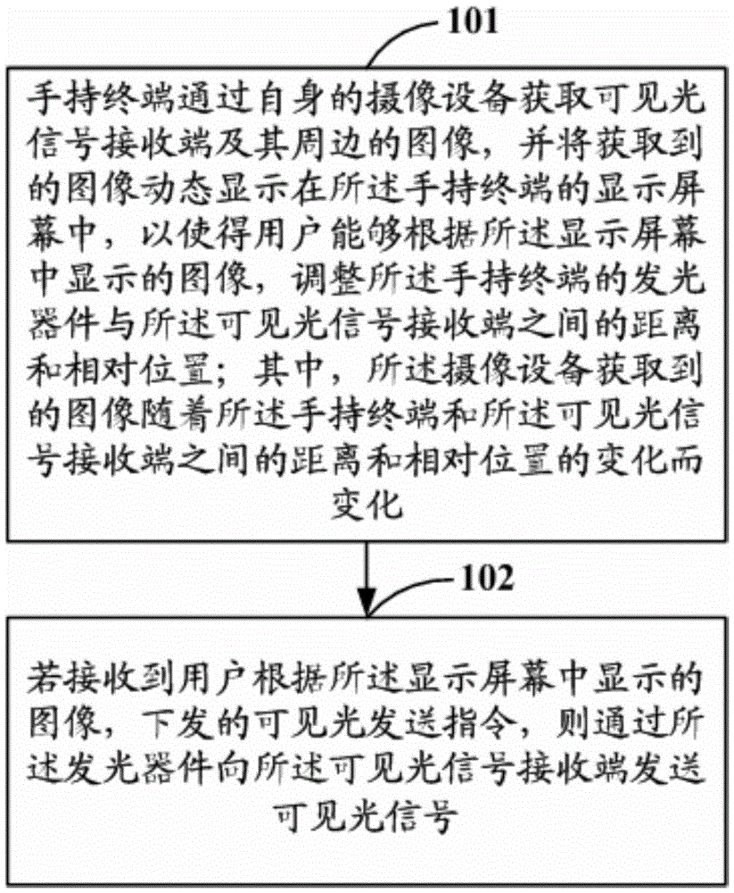
[0032] Embodiment 1 of the present invention provides a visible light communication method, such as figure 1 As shown, it is a schematic flowchart of the visible light communication method described in Embodiment 1 of the present invention, and the method may include the following steps:

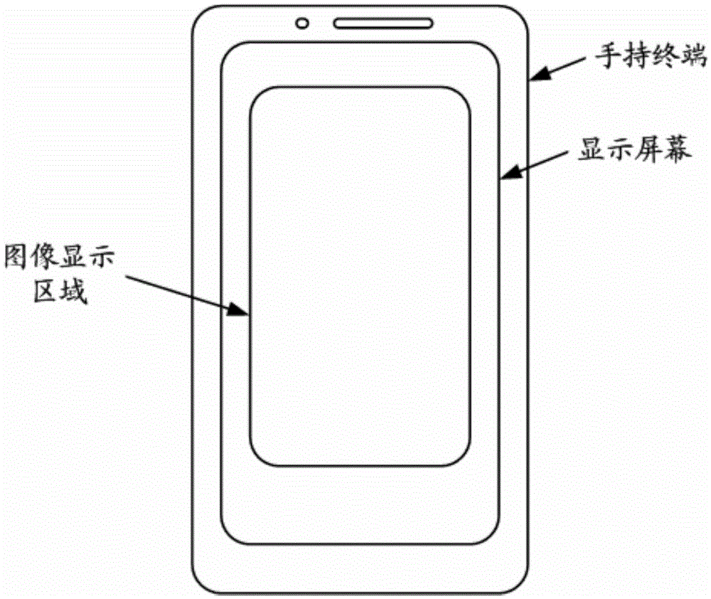
[0033] Step 101: The handheld terminal acquires images of the visible light signal receiving end and its surroundings through its own camera equipment, and dynamically displays the acquired images on the display screen of the handheld terminal, so that the user can image, adjust the distance and relative position between the light-emitting device of the handheld terminal and the visible light signal receiving end; The distance between them and the relative position change.

[0034] That is to say, the user can use the camera equipment of the handheld terminal to obtain images of the visible light signal receiving end and its surroundings, and dynamically display the image through the screen...

Embodiment 2

[0074] Based on the same inventive concept as that of Embodiment 1 of the present invention, Embodiment 2 of the present invention provides a handheld terminal. For the specific implementation of the handheld terminal, please refer to the relevant descriptions in Embodiment 1. Figure 8 As shown, it is a schematic structural diagram of the handheld terminal according to Embodiment 2 of the present invention, and the handheld terminal may include:

[0075] The image acquisition unit 81 can be used to acquire images of the visible light signal receiving end and its surroundings through the imaging device of the handheld terminal; Changes in the distance and relative position between them;

[0076] The image display unit 82 is configured to dynamically display the image acquired by the image acquisition unit 81 on the display screen of the handheld terminal, so that the user can adjust the image of the handheld terminal according to the image displayed on the display screen. the...

Embodiment 3

[0088] Based on the same inventive concept as that of Embodiment 1 of the present invention, Embodiment 3 of the present invention provides a visible light communication system. For specific implementation of the visible light communication system, refer to relevant descriptions in Embodiment 1, and repeated descriptions will not be repeated. Specifically, such as Figure 9 As shown, it is a schematic structural diagram of the visible light communication system described in Embodiment 3 of the present invention. The visible light communication system may include a handheld terminal 91 and a visible light signal receiving end 92, wherein:

[0089] The handheld terminal 91 can be used to acquire images of the visible light signal receiving end 92 and its surroundings through the camera device of the handheld terminal 91, and dynamically display the acquired images on the display screen of the handheld terminal 91, so that The user can adjust the distance and relative position be...


PUM


Abstract

The invention discloses a visible light communication method and system and equipment. Images of a visible light signal receiving end and the periphery of the visible light signal receiving end can be acquired through camera shooting equipment of a hand-held terminal, and dynamically displayed on a display screen of the hand-held terminal, a user can visibly adjust the hand-held terminal through the corresponding images to accurately and efficiently enable the distances and the relative positions between a light emitting device of the hand-held terminal and the visible light signal receiving end to meet set communication conditions, and visible light signals can be sent through simple interaction. Therefore, compared with the prior art, the advantages of being simple in operation process, efficient and good in man-machine interaction experience are achieved.

Description

technical field [0001] The present invention relates to the technical field of visible light communication, in particular to a visible light communication method, device and system. Background technique [0002] Visible light communication technology is a kind of light source device such as LED (Light Emitting Diode, light emitting diode), which uses two states of lighting and extinguishing, and converts data into binary visible light signals and sends them to be transmitted by light signal sensing devices (such as photodiodes, phototransistors, etc.) , photoresistor, etc.) to convert optical signals into electrical signals, and through subsequent circuit and / or software processing, to obtain the corresponding technology for sending data content. [0003] Specifically, using visible light communication technology, for example, using the interaction between a handheld terminal that can send visible light signals and a visible light signal receiving terminal that can receive v...

Claims


Application Information

Patent Timeline
IPC IPC(8): H04M1/725H04B10/116G06F3/048G06F3/041H04M1/72448
CPCH04B10/116G06F3/041G06F3/048H04M1/72448
Inventor 邹骁肖智翔
Owner 邹骁
Why Eureka
Try Eureka