A kind of energy-saving lamp module

A technology of energy-saving lamps and LED lamps, applied in the use of semiconductor lamps, electrical components, electroluminescent light sources, etc., can solve problems such as power waste, and achieve the effect of prolonging life and prolonging life.

Active Publication Date: 2017-08-25
安徽安发特交通工程集团有限公司
View PDF12 Cites 0 Cited by
  • Summary
  • Abstract
  • Description
  • Claims
  • Application Information

AI Technical Summary

Problems solved by technology

[0005] The embodiment of the present invention solves the technical problem of power waste in the prior art by providing an energy-saving lamp module, thereby effectively saving power

Method used


Image

  • A kind of energy-saving lamp module

Examples


Embodiment 1

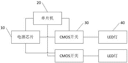
[0024] At the first moment, the single-chip microcomputer 20 sends a first control signal to the power supply chip 10 to control the power supply chip 10 to output the first constant voltage and the first constant current. At the same time, the single-chip microcomputer 20 sends the first control signal to the plurality of CMOS switches respectively. A PWM signal to control the plurality of CMOS switches to perform first PWM dimming of the plurality of LED lamps, and then, at the second moment, the single-chip microcomputer 20 sends a second control signal to the power chip 10 to control the power chip 10 outputs a first constant voltage and a second constant current, wherein the second constant current is smaller than the first constant current, and at the same time, the single-chip microcomputer 20 sends a second PWM signal to a plurality of CMOS switches 30 to control the plurality of CMOS switches 30 performs second PWM dimming on the plurality of LED lamps 40 .

[0025] S...

Embodiment 2

[0027] At the first moment, the single-chip microcomputer 20 sends a first control signal to the power supply chip 10 to control the power supply chip 10 to output a first constant voltage and a first constant current, and at the same time, the single-chip microcomputer 20 sends a first PWM signal to the plurality of CMOS switches 30 respectively. signal to control the plurality of CMOS switches 30 to perform first PWM dimming of the plurality of LED lamps 40 . Then, at the second moment, the single-chip microcomputer 20 sends a third control signal to the first group of CMOS switches 30 in the plurality of CMOS switches 30, and sends a fourth control signal to the second group of CMOS switches 30 to control the first group of CMOS switches 30. The first group of LED lamps linked by the switch are lit within a preset time, and the second group of LED lamps connected to the second group of CMOS switches are controlled to be extinguished within the preset time. At the same time, ...

Embodiment 3

[0030] At the first moment, the single-chip microcomputer 20 sends a first control signal to the power supply chip 10 to control the power supply chip 10 to output the first constant voltage and the first constant current, and the single-chip microcomputer 20 sends the first PWM signal to a plurality of CMOS switches 30 respectively to control The plurality of CMOS switches 30 perform the first PWM dimming on the plurality of LED lamps 40; at the second moment, the single-chip microcomputer 20 sends a second control signal to the power chip 10 to control the power chip 10 to output the first constant voltage and the second constant voltage. Current, the second constant current is less than the first constant current, the single chip microcomputer 20 sends a second PWM signal to the plurality of CMOS switches 30 respectively, so as to control the plurality of CMOS switches 30 to perform the second PWM on the plurality of LED lamps 40 At the same time, at the second moment, the s...


PUM


Abstract

The present invention relates to the technical field of intelligent electronic equipment. By providing an energy-saving lamp module, it includes a power chip, a single-chip microcomputer, a plurality of CMOS switches and a plurality of LED lamps, and the power output end of the power chip is connected to one end of a plurality of CMOS switches. The other end of the switch is connected to a plurality of LED lamps respectively, and the signal control terminals of the single-chip microcomputer are respectively connected to a plurality of CMOS switches and the power supply chip; The first constant current, at the same time, the single-chip microcomputer sends PWM signals to a plurality of CMOS switches respectively, to control a plurality of CMOS switches to carry out PWM dimming to a plurality of LED lamps; The control signal is used to control the power supply chip to output a constant voltage and a second constant current, wherein the second constant current is smaller than the first constant current, thereby effectively saving electric energy and prolonging life.

Description

technical field [0001] The invention relates to the technical field of intelligent electronic equipment, in particular to an energy-saving lamp module. Background technique [0002] The existing lighting control adopts N-level control by PWM to realize multi-level adjustment of lighting, so as to meet the needs of users. [0003] When the PWM is used alone for adjustment, the effective time of turning on the lamp is controlled by controlling the pulse signal, so that the lamp flashes with a certain duty ratio, which effectively saves power. However, because the light is controlled with a certain duty ratio A flashy microcontroller needs to consume a certain amount of power. [0004] Therefore, in the prior art, although the brightness of the light can be adjusted steplessly by using the PWM mode alone to control the light, it still wastes power. Contents of the invention [0005] The embodiment of the present invention solves the technical problem of power waste in the p...

Claims


Application Information

Patent Timeline
Patent Type & Authority Patents(China)
IPC IPC(8): H05B33/08H05B44/00
CPCH05B45/00Y02B20/30
Inventor 邓印武颜棘韩林华
Owner 安徽安发特交通工程集团有限公司
Why Eureka
Try Eureka