Test system and test method for y-branch lithium niobate waveguide phase modulator

A phase modulator and test system technology, which is applied in the direction of testing optical performance, can solve problems such as test errors and inconsistent optical power, and achieve the effects of avoiding test deviations, accurate testing, and improving test accuracy

Active Publication Date: 2009-04-29
BEIJING AEROSPACE TIMES OPTICAL ELECTRONICS TECH
View PDF0 Cites 4 Cited by
  • Summary
  • Abstract
  • Description
  • Claims
  • Application Information

AI Technical Summary

Problems solved by technology

Due to the spectral response characteristics of the built-in detector of the optical power meter, the response rate of the detector to different wavelengths of radiation light is different, resulting in the inconsistency between the output voltage V of the detector and the actual optical power, resulting in test errors

Method used


Image

  • Test system and test method for y-branch lithium niobate waveguide phase modulator
  • Test system and test method for y-branch lithium niobate waveguide phase modulator
  • Test system and test method for y-branch lithium niobate waveguide phase modulator

Examples


Embodiment Construction

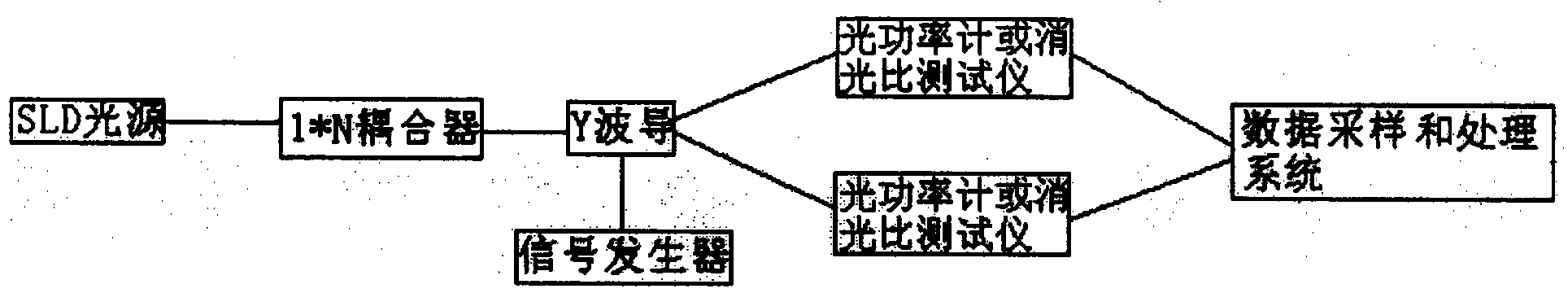
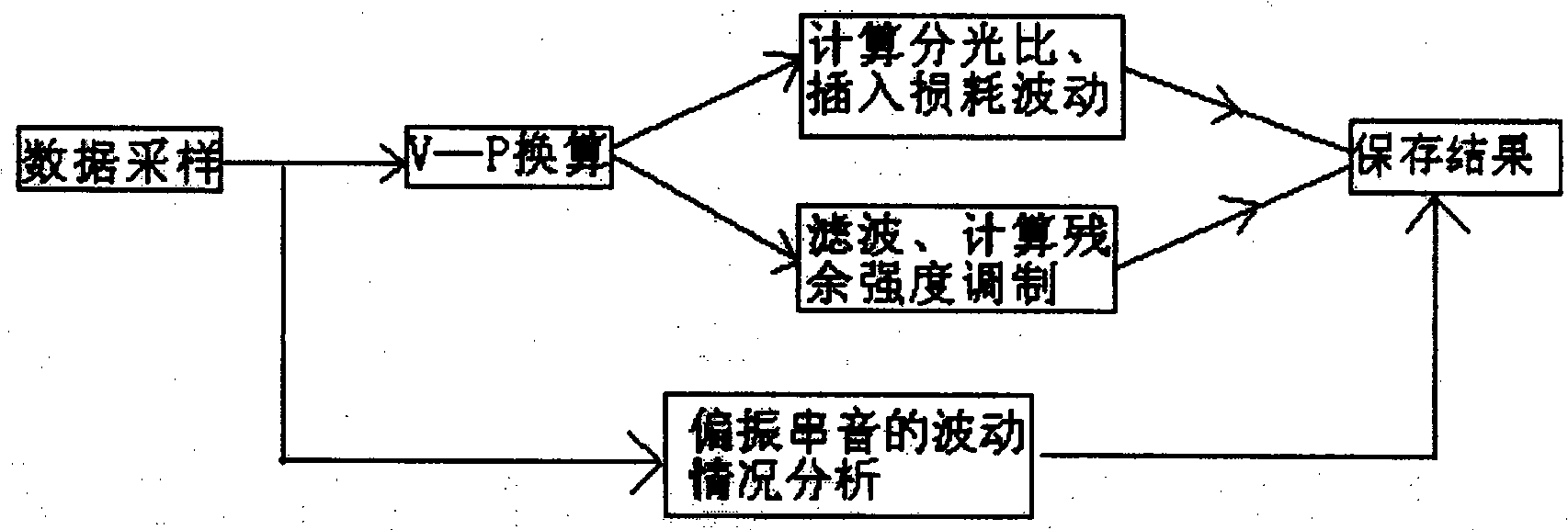
[0025] The test system of the Y-branch lithium niobate waveguide phase modulator (referred to as the Y waveguide), the high-stable SLD light source is split by a 1×N single-mode fiber coupler to couple the light to the input end of the Y waveguide, and the two output ends are connected to the optical power meter or extinction ratio tester. The output of the optical power meter or the extinction ratio tester is written into the computer through the data transmission system. The central wavelength of the SLD light source spectrum changes with the output power, and the response of the output voltage of the power meter to different wavelengths is different. Therefore, when the output power of the SLD is different, there is a nonlinear error in the output of the optical power meter. This error is caused by the difference of the wavelength of the SLD light source with the excitation current (bringing a change in optical power). Only by converting the output voltage V of the optical...


PUM


Abstract

A test system and a test method for a Y-branch lithium niobate waveguide phase modulator. The light source is split by a 1×N single-mode fiber coupler to couple the light to the input end of the Y waveguide, and the two output ends are connected to an optical power meter or an extinction ratio tester. The output of the optical power meter or the extinction ratio tester is written into the computer through the data transmission system, and the P~V quadratic nonlinear relationship is fitted according to the test data, and the output voltage V of the optical power meter is converted into the calibrated optical power P, which is substituted into The formula calculates the insertion loss fluctuation and the splitting ratio of the Y waveguide. Add the periodic signal of the required specific frequency, amplitude and waveform to the modulation electrode of the Y waveguide, filter in the modulation signal band, and calculate the residual intensity modulation of the Y waveguide. The invention can continuously sample data, continuously monitor multiple Y waveguide devices, measure parameters such as optical power, insertion loss fluctuation, splitting ratio, polarization crosstalk, and residual intensity modulation, and ensure data accuracy during the sampling process.

Description

technical field [0001] The invention relates to a test system and a test method of a Y waveguide, which are used for testing the fluctuation of the insertion loss, splitting ratio, polarization crosstalk and residual intensity modulation of the Y waveguide. Parameters such as pigtail output power and polarization crosstalk can also be tested for other integrated optics. Background technique [0002] The Y-branch lithium niobate waveguide phase modulator is a Y-branch-shaped strip waveguide made by proton exchange annealing technology on an X-cut Y-pass lithium niobate wafer. Utilizing the electro-optic characteristics of the lithium niobate material itself, the phase of the guided light can be changed by changing the refractive index in the waveguide region by an external electric field, so as to achieve the purpose of modulating the phase. The residual intensity modulation of the Y waveguide is an additional effect of the phase modulation. When the external electric field...

Claims


Application Information

Patent Timeline
Patent Type & Authority Patents(China)
IPC IPC(8): G01M11/02
Inventor 王巍徐宇新李瑞龙相艳荣李晶
Owner BEIJING AEROSPACE TIMES OPTICAL ELECTRONICS TECH
Why Eureka
Try Eureka