Pneumatic type precise corn no-tillage planter

A pneumatic, seeder technology, applied in the directions of seeder parts, seeding, fertilizer and seeding equipment, etc., can solve the problems of spring adjustment and lower limit, give a reasonable solution, seeder damage, easy congestion and other problems, to ensure seeding. The effect of deep consistency, smooth work and stable contact

Active Publication Date: 2016-06-15
CHINA AGRI UNIV
View PDF12 Cites 6 Cited by
  • Summary
  • Abstract
  • Description
  • Claims
  • Application Information

AI Technical Summary

Problems solved by technology

Corn no-tillage sowing in the Huang-Huai-Hai area has problems such as high straw toughness, easy congestion, unstable sowing depth, and inconvenient adjustment of the tension spring of the traditional parallel four-bar linkage mechanism. At the same time, the parallel four-bar linkage mechanism has no active lower limit function during transportation. If the distance between the road surfaces is too small, the bumps and undulations of the road surface will easily cause the seeder to collide with the road surface and cause damage
[0003] In addition, the airflow distribution of pneumatic seeders in the prior art mostly adopts equal-diameter air ducts, which may easily cause the problem of reseeding at high pressure and missed seeding at low pressure
[0004] At present, the main domestic seeders use mechanical seed metering devices, which have low seeding speed and poor seeding accuracy.
Seeder profiling mechanism CN103688627A adopts cross-axis profiling, a single-body imitation rice and wheat double-purpose precision hole planter CN104067706A, a profiling sowing device CN204907056U, a frame-type parallel four-bar profiling mechanism CN86207593U, a seeder profiling mechanism CN105210488A all adopt parallel four-bar linkage mechanism, but none of them gives a reasonable solution to the problem of spring adjustment and lower limit

Method used


Image

  • Pneumatic type precise corn no-tillage planter
  • Pneumatic type precise corn no-tillage planter
  • Pneumatic type precise corn no-tillage planter

Examples


Embodiment Construction

[0110] The specific implementation manners of the present invention will be further described in detail below in conjunction with the accompanying drawings.

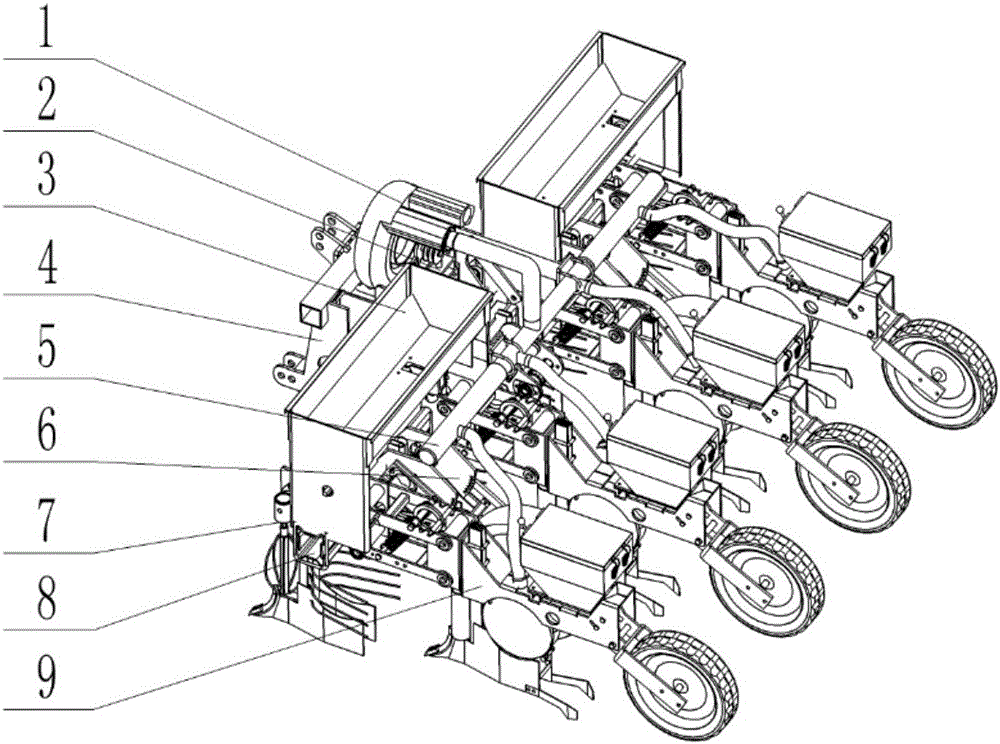
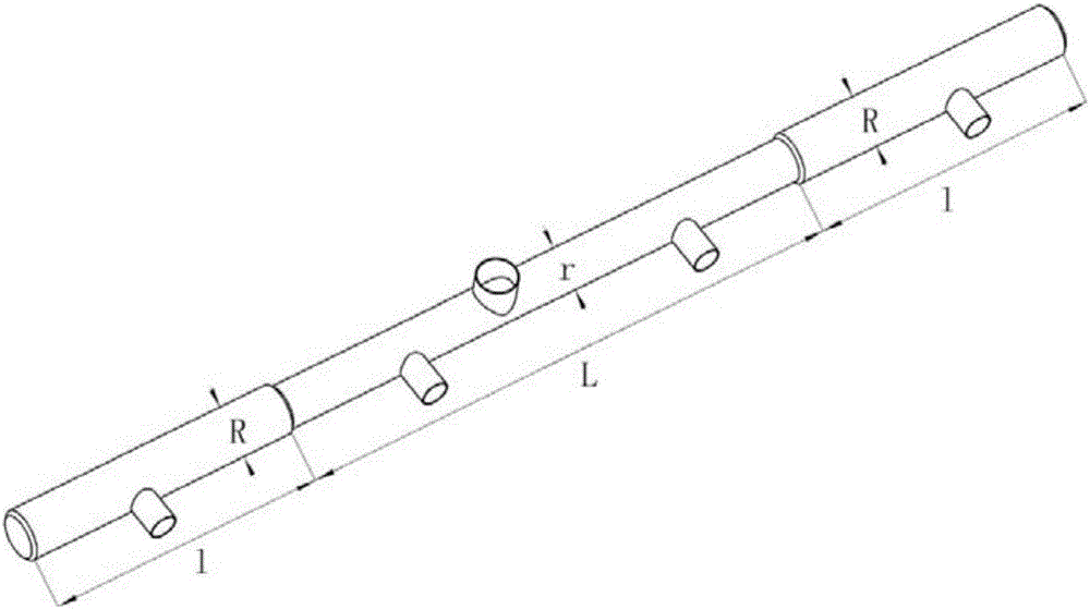
[0111] Such as figure 1 As shown, a pneumatic corn precision no-tillage seeder includes fan 1, fan rack 2, fertilizer box 3, three-point suspension mechanism 4, air pressure distribution pipe 5, depth limiting mechanism 6, and active anti-blocking mechanism 7 , universal frame 8 and parallel four-bar linkage seeding mechanism 9.

[0112] The general-purpose frame 8 is a hollow beam, the middle part of the front end of the beam is connected with a three-point suspension mechanism 4, a plurality of active anti-blocking mechanisms 7 are connected under the front end, and a plurality of parallel four-bar linkage seeding mechanisms 9 and depth-limiting mechanisms are connected under the rear end of the beam. 6, and the active anti-blocking mechanism 7 and the parallel four-bar linkage seeding mechanism 9 are arranged in a st...


PUM


Abstract

The invention belongs to the technical field of agricultural machinery, and relates to a pneumatic type precise corn no-tillage planter. The pneumatic type precise corn no-tillage planter comprises a fan (1), a fan rack (2), a fertilizer box (3), a three-point hanging mechanism (4), an active anti-blocking mechanism (7), a general stander (8), a parallel four-connection-rod seeding mechanism (9), an air pressure distribution pipe (5) and a depth control mechanism (6), wherein the four-connection-rod seeding mechanism (9) further comprises a tension spring adjustment ring (29), a stop piece (37) and a lower parallel four-connection-rod limiting mechanism (38); and the depth control mechanism (6) comprises a depth control mechanism mounting plate (46), a depth control mechanism rotating shaft (47), a spring fixing pin (48), an adjustment spring (49), a depth control mechanism adjustment handle (50), a limiting plate (51), a depth control wheel (52), a first depth control mechanism bevel gear transmission box (17) and a second depth control mechanism bevel gear transmission box (56). The planter integrates the active anti-blocking mechanism, a pneumatic type planter and seeding profiling.

Description

technical field [0001] The invention belongs to the technical field of agricultural machinery, and in particular relates to a pneumatic corn precision no-tillage seeder. Background technique [0002] As the main agricultural equipment now, the seeder has a major impact on the current agricultural production. Corn no-tillage sowing in the Huang-Huai-Hai area has problems such as high straw toughness, easy congestion, unstable sowing depth, and inconvenient adjustment of the tension spring of the traditional parallel four-bar linkage mechanism. At the same time, the parallel four-bar linkage mechanism has no active lower limit function during transportation. If the distance between the road surfaces is too small, the bumps and undulations of the road surface will easily cause the seeder to collide with the road surface and cause damage. [0003] In addition, in the prior art, the airflow distribution of pneumatic seeders mostly adopts equal-diameter air ducts, which may easil...

Claims


Application Information

Patent Timeline
Patent Type & Authority Applications(China)
IPC IPC(8): A01C7/06A01C7/20
CPCA01C7/06A01C7/20A01C7/203Y02P60/20
Inventor 张东兴颜丙新杨丽崔涛张瑞李克鸿殷小伟
Owner CHINA AGRI UNIV
Why Eureka
Try Eureka