Triangular pipe wall blade type static mixer
A static mixer, triangular tube technology, applied in the direction of fluid mixer, mixer, chemical instruments and methods, etc., can solve the problems of complex mixing element structure, large pressure drop in the mixing process, complex processing, etc., and achieve low resistance, The effect of saving energy consumption and simple blade structure
- Summary
- Abstract
- Description
- Claims
- Application Information
AI Technical Summary
Problems solved by technology
Method used
Image

Examples
Embodiment 1
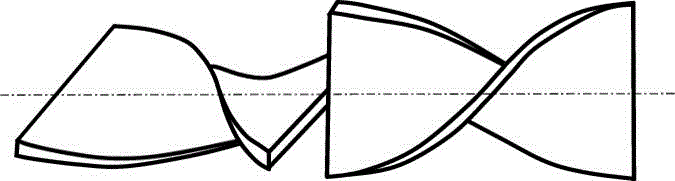
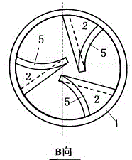
[0048] Depend on figure 2 and image 3 It can be seen that the basic unit section is composed of a round tube and three triangular tube wall blades welded on its inner wall. The solid line part in the figure is the blade, and the dotted line or dotted line part is the round tube; the right figure is the axonometric view of the left figure (viewed from right to left).
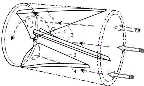
[0049] The production of leaves see Figure 4 , each blade is taken from the circumscribed circular tube; when making, take a section of circular tube (determine the height of the tube according to the design size of the blade), and cut it on the tube wall according to the dotted line to form a vertical plane 3; Scribing cuts to form arc surface 4 (arc surface 4 is kept perpendicular to the wall of the tube), and remains perpendicular to the axis to form bottom surface 5. The length of the bottom surface depends on the blade angle and size of the design; vertical surface 3 is at right angles to bottom surface...
Embodiment 2
[0054] In the process of engineering design and specific implementation, the following aspects should be grasped:
[0055] (1) The static mixer created by the present invention is based on the basic unit section in use, and each (or every two) unit sections are processed with flanges at both ends, and each (or each group) of mixing units is connected by flanges, The blade rotation of adjacent unit sections or adjacent mixing units can be changed to reverse stagger.
[0056] (2) Determine the size of the blade according to the characteristics and concentration of the main fluid material to be mixed, as well as the type and amount of the mixed material. leaf size finger Figure 5 In "the length of the vertical surface 3 and the arc length of the arc surface 5", the ratio of the lengths of the two determines the "length of the surface 4" and "the angle formed by the surface 4 and the surface 3" (also used in blade manufacturing and processing) Called the cutting angle α). Amon...
Embodiment 3
[0060] Experimental device: in order to measure the present invention to create static mixer effect by experiment, set up as Figure 15 experimental device. Figure 4 is the tested static mixer unit, and each mixer uses 2 unit sections. 1 is a stainless steel water tank; 2 is a small medium-concentrated slurry pump; 3 is a flow meter; 5 is a valve; 6 is a pressure gauge. It mainly measures the pressure drop, flow rate change and distribution of fluid materials passing through the mixing unit, and the slurry hanging situation. The static mixer unit to be tested adopts two kinds, one is a mixer with 2 unit sections created by the present invention; the other is a standard static mixer—Kenics static mixer with 2 sets of mixing unit elements. The material is plexiglass, customized processing.
[0061] The purpose of the experiment: to compare the pressure, flow rate change and distribution, and slurry hanging of the two mixers.
[0062] Experimental conditions: The material use...
PUM
 Abstract
Description
Claims
Application Information
 - Generate Ideas
- Intellectual Property
- Life Sciences
- Materials
- Tech Scout
- Unparalleled Data Quality
- Higher Quality Content
- 60% Fewer Hallucinations
Browse by: Latest US Patents, China's latest patents, Technical Efficacy Thesaurus, Application Domain, Technology Topic, Popular Technical Reports.
© 2025 PatSnap. All rights reserved.Legal|Privacy policy|Modern Slavery Act Transparency Statement|Sitemap|About US| Contact US: help@patsnap.com