Unlock instant, AI-driven research and patent intelligence for your innovation.

Cooling device for production of aluminum composite plate

The technology of an aluminum composite panel and a cooling device is applied in the field of cooling devices, which can solve the problems of uneven cooling and uneven air output of the aluminum composite panel, and achieve the effects of simple structure, uniform cooling and low cost.

Active Publication Date: 2016-06-15
JIANGSU ORIENTAL BAO TAI TECH CO LTD
View PDF6 Cites 6 Cited by
  • Summary
  • Abstract
  • Description
  • Claims
  • Application Information

AI Technical Summary

Problems solved by technology

[0004] However, the air duct of the existing cooling device includes an outer cover, and a plurality of cold air outlets are arranged at the lower end of the outer cover, but since the cold air inlet is located in the middle of the upper end of the outer cover, after entering the inside of the outer cover, most of the cold air will flow from the middle of the outer cover. The cold air outlet flows out, and the cold air flowing out from the cold air outlets on both sides is less, so the air volume will be uneven, which will cause the problem of uneven cooling of the aluminum composite panel

Method used


Image

  • Cooling device for production of aluminum composite plate
  • Cooling device for production of aluminum composite plate

Examples


Embodiment 1

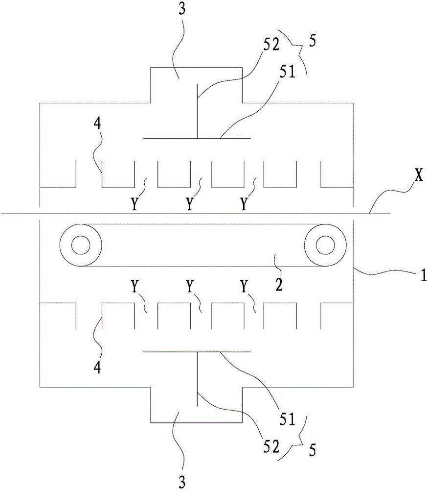
[0025] like figure 1 As shown, the cooling device for the production of aluminum composite panels provided in this embodiment includes a box body 1 with an inlet and an outlet; it is located in the box body 1 for driving the aluminum composite panel X to enter and exit from the inlet. The conveying unit 2 from the feed port; the air supply unit (not shown in the figure); and the air duct 3 used to connect the air supply unit with the box body 1; wherein the outlet of the air duct 3 is located at the top of the box body 1 for cooling The device also includes a plurality of partition plates 4 perpendicular to the moving direction of the aluminum composite panel X and located above the conveying unit 2. The plurality of partition plates 4 are spaced apart and arranged side by side. When the cooling device is working, the wind blows After entering the box body 1 from the air channel 3 , it blows to the surface of the aluminum composite panel X from the gap Y between every two adja...

Embodiment 2

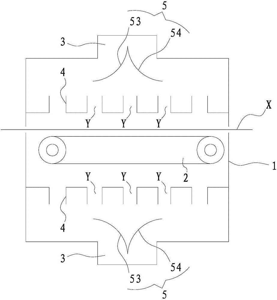
[0036] like figure 2 As shown, the structure of the cooling device involved in this embodiment is basically the same as that of Embodiment 1. The difference is that the flow distribution assembly 5 in this example includes a set of outlets in the middle of the air duct 3 from top to bottom, and to both sides. The curved first arc-shaped plate 53 and the second arc-shaped plate 54, the upper ends of the first arc-shaped plate 53 and the second arc-shaped plate 54 are fixed and integrated, and separate the two adjacent pieces directly below the outlet of the air duct 3 The gap Y between the plates 4 is shaded.

[0037] Specifically, the first arc-shaped plate 53 and the second arc-shaped plate 54 are arranged symmetrically. The split is relatively even.

[0038] To sum up, after the cooling device used in this application, the wind first spreads to the periphery of the box through the splitter assembly, and then through the evenly distributed gaps, the front and back sides of...


PUM


Abstract

The invention discloses a cooling device for production of an aluminum composite plate. The cooling device comprises a box body with a feed inlet and a discharge outlet, a conveying unit, an air supply unit and an air flue. The conveying unit is located in the box body and used for driving the aluminum composite plate to enter the feed inlet and get out of the discharge outlet. The air flue is used for communicating the air supply unit with the box body. The outlet of the air flue is located in the top of the box body. The cooling device further comprises a plurality of partition plates in the direction perpendicular to the moving direction of the aluminum composite plate and located above the conveying unit. The partition plates are arranged at intervals side by side. When the cooling device works, air enters the box body from the air flue and then is blown to the surface of the aluminum composite plate from the gap between every two adjacent partition plates. Under the effect of the partition plates, air entering the box body can be scattered around and then is blown to the aluminum composite plate located on the conveying unit, the aluminum composite plate is evenly cooled, and the cooling device is simple in structure, convenient to operate and low in cost.

Description

technical field [0001] The invention belongs to the field of aluminum composite board production equipment, and in particular relates to a cooling device for producing aluminum composite boards. Background technique [0002] As we all know, in the production process of aluminum composite panels, the raw materials need to be proportioned according to the design, and the materials, [0003] Mixing and stirring, extrusion molding, drying, cooling, and receiving (coiled or cut into sections). [0004] However, the air duct of the existing cooling device includes an outer cover, and a plurality of cold air outlets are arranged at the lower end of the outer cover, but since the cold air inlet is located in the middle of the upper end of the outer cover, after entering the inside of the outer cover, most of the cold air will flow from the middle of the outer cover. The cold air outlet flows out, and the cold air flowing out from the cold air outlets on both sides is less, so the a...

Claims


Application Information

Patent Timeline
Patent Type & Authority Applications(China)
IPC IPC(8): B21C29/00
CPCB21C29/003
Inventor 蔡承刚
Owner JIANGSU ORIENTAL BAO TAI TECH CO LTD
Features
  • R&D
  • Intellectual Property
  • Life Sciences
  • Materials
  • Tech Scout
  • Unparalleled Data Quality
  • Higher Quality Content
  • 60% Fewer Hallucinations
Learn More