

Press-fitting device for a stepped type needle roller bearing without inner ring
A technology of needle roller bearings and press-fitting devices, which is applied in the direction of shafts and bearings, shafts, crankshafts, etc., and can solve problems such as easy tilting of bearings and inability to complete press-fitting
- Summary
- Abstract
- Description
- Claims
- Application Information
AI Technical Summary
Problems solved by technology
Method used
Image

Examples
Embodiment 1
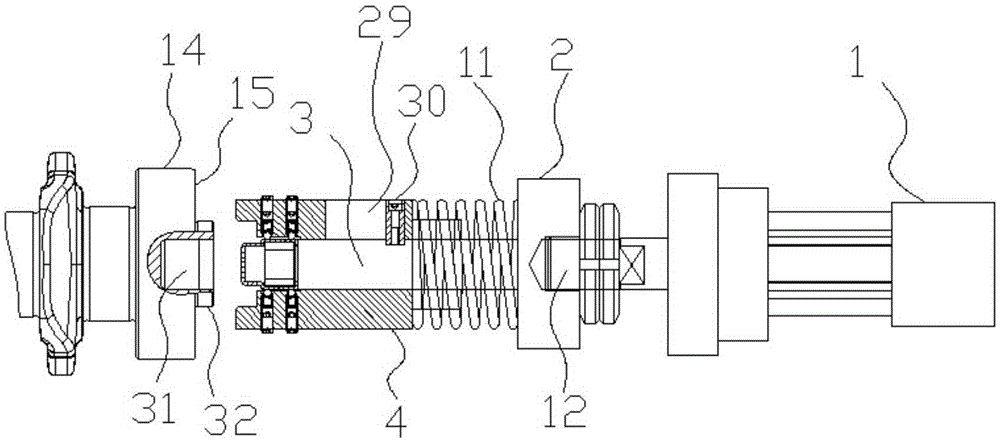
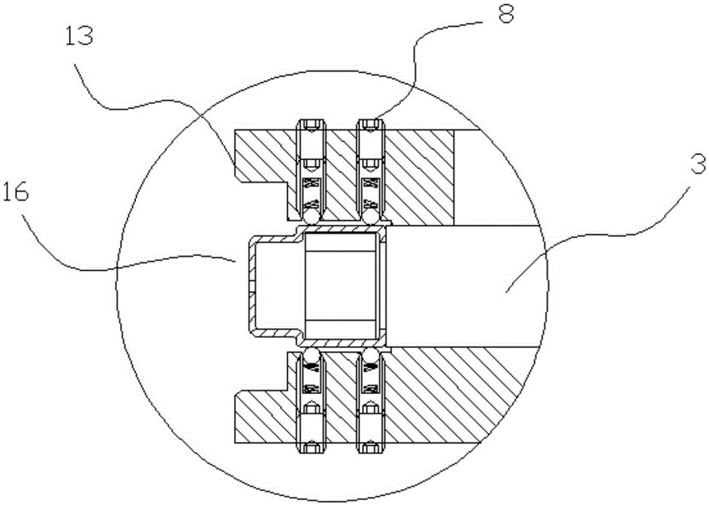
[0029] Embodiment 1: as figure 1 , figure 2 , image 3 , Figure 4 , Figure 5 , Figure 6 , Figure 7In the shown embodiment, a step-type needle roller bearing press-fitting device without an inner ring includes a bearing press-fit base and a power electric cylinder 1, and the bearing press-fit base includes a force transmission seat 2, a bearing push rod 3. The end of the bearing push rod 3 close to the power electric cylinder 1 is the rear end of the bearing push rod 3. The power transmission seat 2 is connected to the rear end of the bearing push rod 3. The power electric cylinder 1 has a piston rod, and the piston rod The protruding direction of the bearing is towards the force transmission seat 2, and the outer positioning sleeve 4 that is slidingly connected with the bearing push rod 3 and coaxial is set on the bearing push rod 3, and the outer positioning sleeve 4 is provided with a matching inner hole 5. The preset inner hole 6, the matching inner hole 5 and th...
Embodiment 2
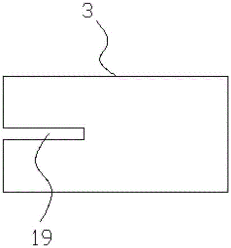
[0033] Embodiment 2: the basic structure and implementation mode of this embodiment are the same as embodiment 1, and its difference is, as Figure 8 , Figure 9 As shown in , the outer positioning sleeve 4 is provided with an inner chute 19, and the outer positioning sleeve 4 is provided with an adjustment main rod 20 that can slide in the inner chute 19, and the adjustment main rod 20 Through the axis of the outer positioning sleeve 4 and perpendicular to the axis of the outer positioning sleeve 4, both ends of the adjusting main rod 20 are outside the outer positioning sleeve 4, and two self-adjusting parts are respectively arranged at the two ends of the adjusting main rod 20. The self-adjusting part includes an outer horizontal connecting rod 21, a vertical connecting rod 22 connected to the outer horizontal connecting rod 21, a self-adjusting horizontal round rod 23 connected to the vertical connecting rod 22, and two self-adjusting rods belonging to the two self-adjusti...
Embodiment 3
[0039] Embodiment 3: the basic structure and implementation mode of this embodiment are the same as embodiment 2, and its difference is, as Figure 10 , Figure 11 As shown in , the outer ring limiting rod 24 is slidingly connected with the adjusting main rod 20 , the sliding direction is horizontal, and the inner end of the outer ring limiting rod 24 is connected to the outer positioning sleeve 4 . The outer ring limit rod 24 is slidingly connected with the adjusting main rod 20, which ensures that the outer ring limit rod 24 can move toward the bearing hole 31 along with the bearing to be press-fitted. During the process, the outer ring limit rod 24 still provides the self-aligning and centering function for the bearing to be pressed at all times. When the bearing to be pressed has a tendency to tilt, the outer ring limit rod 24 will completely lock the inclination angle of the bearing to be pressed. It fully guarantees the horizontality of the bearing to be pressed during ...
PUM
 Abstract
Description
Claims
Application Information