Optical film coating device

An optical coating and flange technology, applied in optics, optical components, sputtering coating, etc., can solve the problems affecting the quality of the coating, and achieve the effect of stable connection and not easy to tilt

Inactive Publication Date: 2009-12-23
HONG FU JIN PRECISION IND (SHENZHEN) CO LTD +1
View PDF0 Cites 7 Cited by
  • Summary
  • Abstract
  • Description
  • Claims
  • Application Information

AI Technical Summary

Problems solved by technology

When there is wear between the screw and the screw hole or the strength of the installation screw is uneven, it is easy to cause the substrate carrier to tilt relative to the rotation axis, thus affecting the coating quality

Method used


Image

  • Optical film coating device
  • Optical film coating device
  • Optical film coating device

Examples


Embodiment Construction

[0013] The present invention will be further described in detail below with reference to the accompanying drawings.

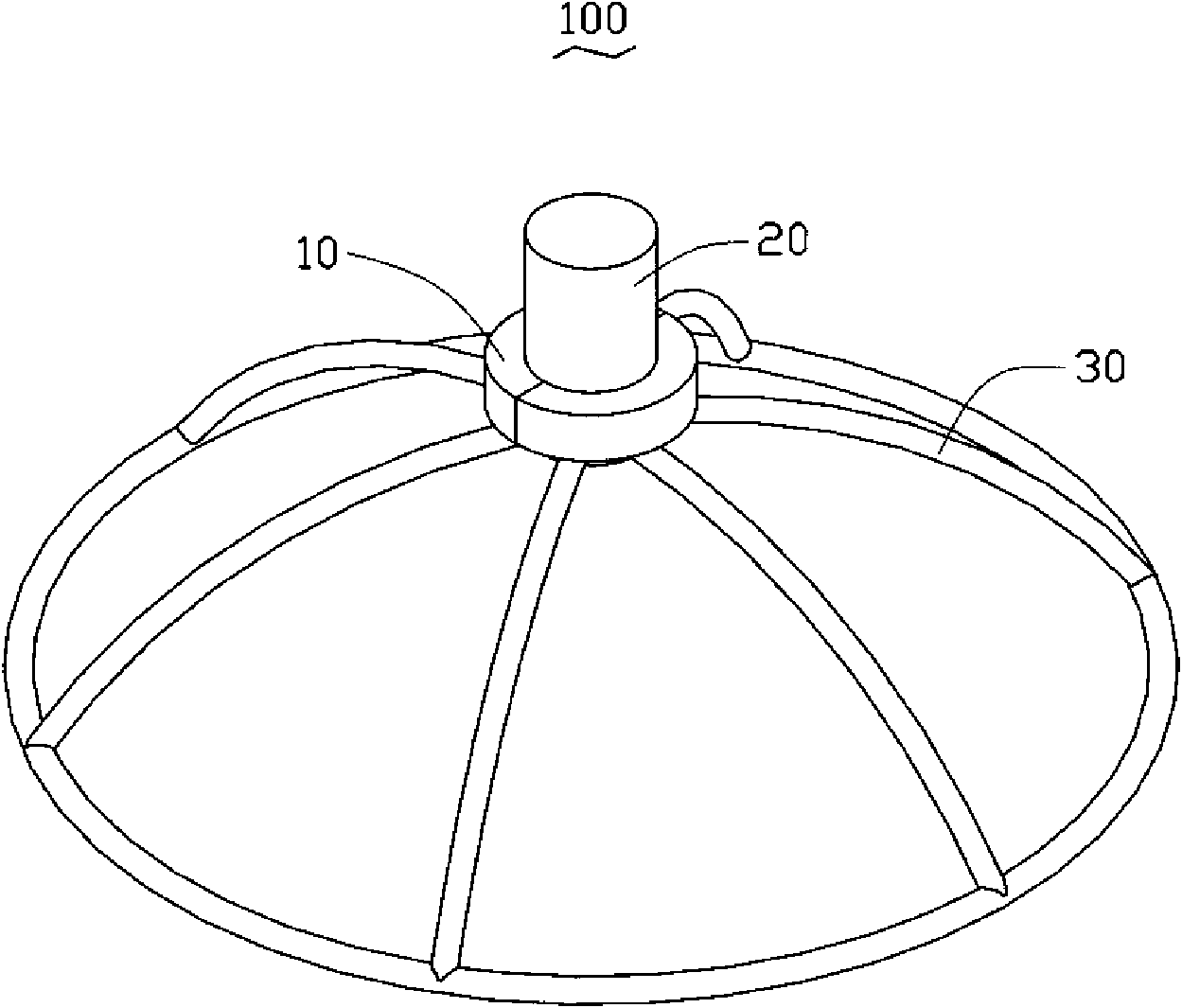
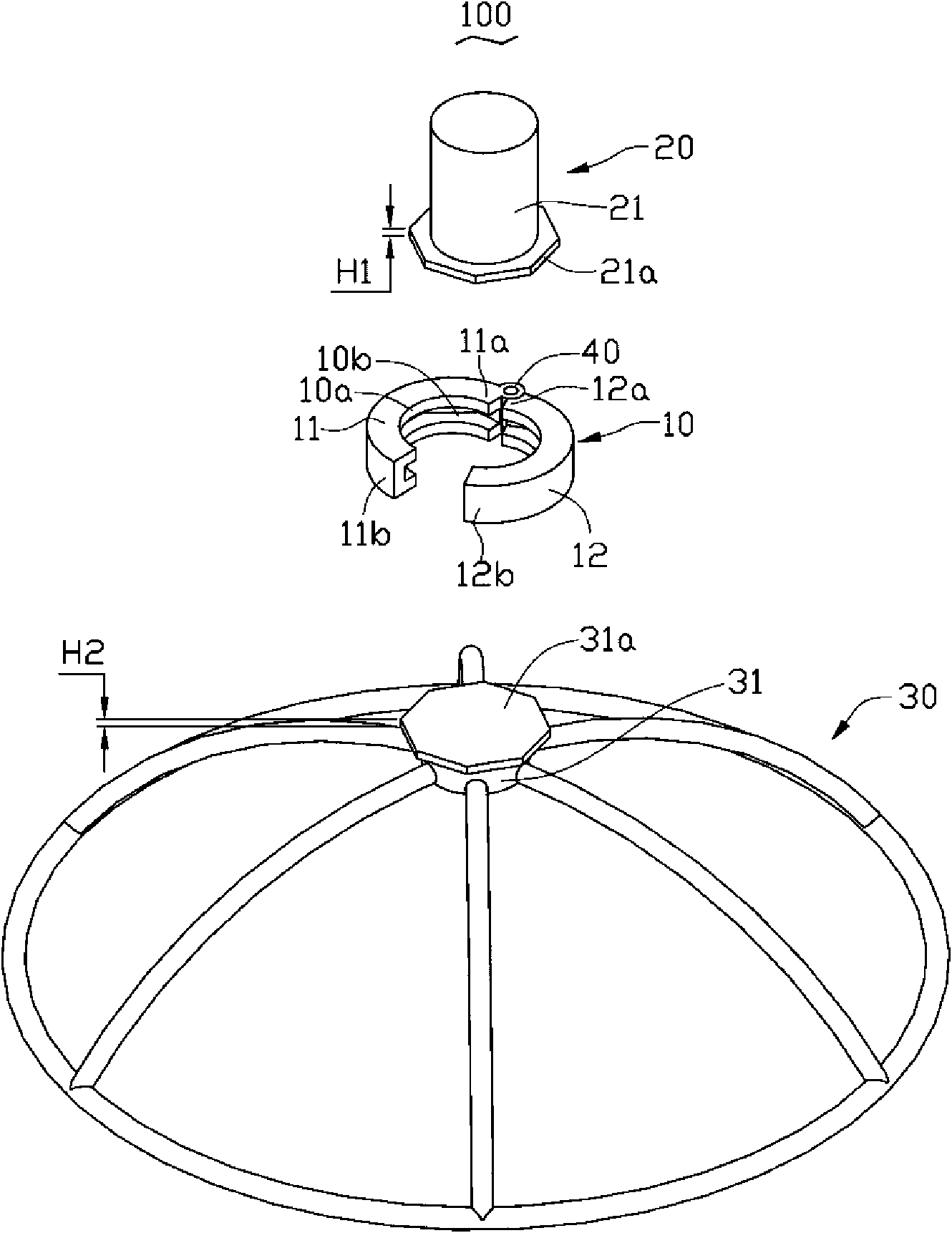
[0014] see figure 1 , the first embodiment of the present invention provides an optical coating device 100 . The optical coating device 100 includes a snap ring 10 , a rotating shaft 20 and a substrate carrier 30 .

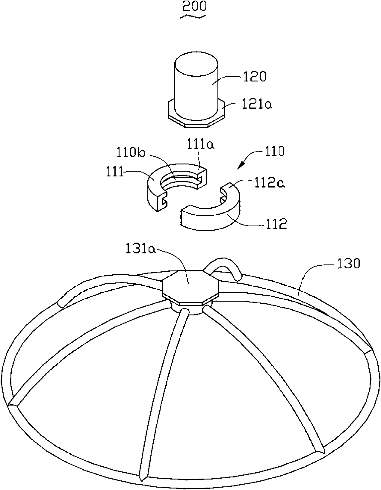
[0015] see figure 2 , the inner annular surface 10a of the snap ring 10 has a groove 10b. The groove 10b of the snap ring 10 may have geometric shapes such as a circle, an ellipse or a regular polygon. In this embodiment, the snap ring 10 is circular. In order to facilitate the transmission of torque and the uniform force, the groove 10b adopts a regular octagon. The snap ring 10 includes a first half ring 11 and a second half ring 12 . The first half ring 11 has a first end 11a and a second end 11b. The second half ring 12 has a third end 12a and a fourth end 12b. The first end 11a and the third end 12a are hinged. In this embodiment, the...


PUM


Abstract

The invention relates to an optical film coating device which comprises a rotating shaft, a substrate supporting frame and a clamping ring, wherein one end of the rotating shaft is provided with a first flange; the substrate supporting frame is provided with a second flange; a groove is arranged around the inner ring surface of the clamping ring; the first flange and the second flange are contained in the groove; and the clamping ring comprises a first semi ring and a second semi ring which can be connected mutually. By clamping the two flanges of the rotating shaft and the substrate supporting frame into the groove of the clamping ring, the optical film coating device provided by the invention ensures that the substrate supporting frame is connected stably relative to the rotating shaft and does not incline easily.

Description

technical field [0001] The invention relates to an optical coating device for coating. Background technique [0002] At present, optical films are widely used in optical instruments, such as sensors, semiconductor lasers, interferometers, glasses and optical fiber communication components and many other fields. Optical thin films usually achieve their desired effects through interference, that is, coating one or more layers of dielectric films or metal films on optical components or independent substrates to change the transmission characteristics of light waves. [0003] At present, the production of optical thin films is usually based on physical vapor deposition. This method is to convert the thin film material from solid state to gaseous or ionic state. The gaseous or ionic material passes through the space from the evaporation source and reaches the surface of the substrate. , will deposit and gradually form a thin film. Generally, in order to produce high-purity thin...

Claims


Application Information

Patent Timeline
Patent Type & Authority Applications(China)
IPC IPC(8): C23C14/24G02B1/10
CPCC23C14/505
Inventor 王仲培
Owner HONG FU JIN PRECISION IND (SHENZHEN) CO LTD
Why Eureka
Try Eureka