Production device for cement pipes

A technology for production devices and cement pipes, which is applied to ceramic molding machines, molds, manufacturing tools, etc., can solve the problems of increasing the difficulty of product production and subsequent maintenance, prolonging the production cycle of products, increasing the space occupied by equipment, etc., to increase production efficiency. and quality, reducing the difficulty of post-maintenance, and reducing the overall space occupied

Active Publication Date: 2016-06-15
高唐县鼎力建筑机械有限公司
View PDF7 Cites 7 Cited by
  • Summary
  • Abstract
  • Description
  • Claims
  • Application Information

AI Technical Summary

Problems solved by technology

[0002] Chinese patent CN103144189B (hereinafter referred to as "reference document") discloses a cement pipe manufacturing equipment. It is undeniable that the reference document has a high degree of automation, but due to its structural defects, such as: the power connection between the mandrel and the drive mechanism; The mold is directly connected with the compression fixture, etc.
This technical solution has the following serious defects: 1. When the material enters the inner cavity, the core mold is in a moving state, and the material is poured from the top of the outer mold, and then the core mold moves from the bottom to the upper part, so that the material enters the gap between the core mold and the outer mold. In the cavity between the mandrel, this technical solution can be realized in theory, but in fact, this technical solution greatly increases the difficulty and time of cement pipe forming, because, in the state of mandrel movement, a large amount of material is squeezed out. mold, and the material in the cavity is extremely loose. Even if a vibration mechanism is installed in the core mold, the simple vibration cannot reduce the difficulty and time of production. Even so, the comparison file needs auxiliary equipment to be realized, such as installing Pusher, pusher power mechanism, etc.; 2. The structure is bloated and occupies a very large area. As we all know, cement pipe products are generally used in pipeline equipment, and their weight ranges from a few hundred kilograms to a thousand kilograms, and as little as 2- 3 meters, more than 3-6 meters, since the mandrel is in a moving state, it is inevitable that the drive mechanism occupies the same height as the mandrel, which greatly increases the height of the product and increases the space occupied by the equipment. At this time, all The prepared cement pipe is extremely difficult to remove! And it also needs reinforcement facilities for the mandrel, such as mandrel pillars, guide posts, etc. in the comparison document, which increases the difficulty of product production and subsequent maintenance! The technical scheme of connecting the outer mold and the compression fixture adopted in the comparison document results in the material entering the cavity only from the opening of the fixed compression fixture, resulting in a longer production cycle and an overly complex structure that requires other structures to assist. Such as aggregate baffles, etc., which greatly reduces production efficiency and increases the difficulty of later maintenance, and it can only be used for the preparation of a single cement pipe
[0003] Due to the low efficiency of making cement pipes by comparison documents, and due to the complex and bloated structure, the production cost of equipment is relatively high, and because the maintenance of comparison documents is difficult in the later stage, it is necessary to provide a cement pipe production equipment that is more efficient and simple in structure

Method used


Image

  • Production device for cement pipes
  • Production device for cement pipes
  • Production device for cement pipes

Examples


Embodiment Construction

[0029] The patent of this case will be further described below in conjunction with the accompanying drawings. Obviously, this specific embodiment is only a further description of the present invention, and should not be construed as limiting the technical solution of the patent of this case. On the basis of the structure or principle provided by the present invention Various modifications can be extended, and these modified technical solutions are all within the protection scope of the present invention.

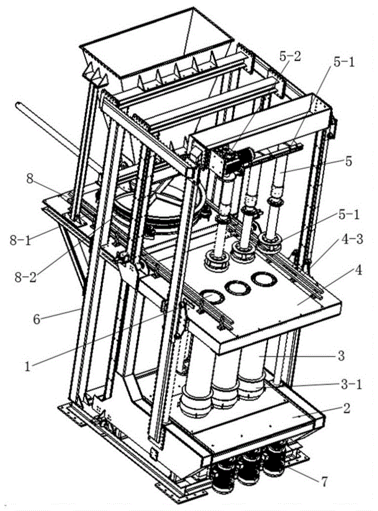
[0030] Such as Figure 1-5 Shown, a kind of cement pipe production device comprises:

[0031] Mandrel 1; the shape of the mandrel 1 is determined according to the shape of the prepared cement pipe. If a circular cement pipe is prepared, the mandrel 1 is cylindrical. If a square cement pipe is prepared, the mandrel 1 is square.

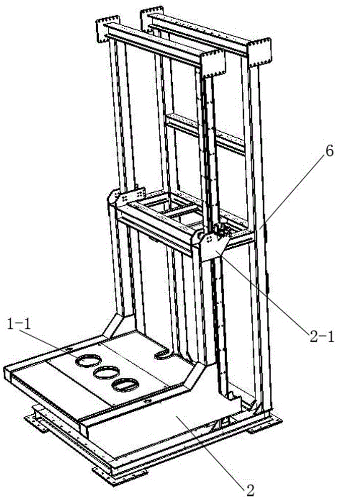
[0032] Cement pipe lifting platform 2, the cement pipe lifting platform 2 is provided with a mandrel through hole 1-1, the mandrel through hole 1-1...


PUM


Abstract

The invention provides a production device for cement pipes. The production device for cement pipes comprises a core mold, a cement pipe lifting platform, an outer mold with an inner cavity, an outer mold fixing platform, a cement squeezing device and a machine body, wherein the cement squeezing device is fixedly installed above the machine body through a lifting device; the outer mold fixing platform is fixedly installed on the part, below the cement squeezing device, of the machine body through a lifting device; the cement pipe lifting platform is fixedly installed on the part, below the outer mold fixing platform, of the machine body through a lifting device. According to the production device for cement pipes, the core mold is in a fixed state, so that the overall occupied space is greatly reduced; cement pipe materials enter from the top of the outer mold and directly flow into a forming cavity under the action of gravity, the time for manufacturing cement pipes is shortened, the manufacturing efficiency of the cement pipes is greatly increased, and the compactness of the cement materials is increased. The structure is simple. The demolding procedure for manufacturing cement pipes is simple, and the manufacturing efficiency is high. The number of core molds, outer molds and cement squeezing devices can be increased in an unlimited mode, and cement pipes can be produced in a batch mode.

Description

technical field [0001] The invention relates to a cement pipe production device. Background technique [0002] Chinese patent CN103144189B (hereinafter referred to as "reference document") discloses a cement pipe manufacturing equipment. It is undeniable that the reference document has a high degree of automation, but due to its structural defects, such as: the power connection between the mandrel and the drive mechanism; The mold is directly connected with the compression fixture and so on. This technical solution has the following serious defects: 1. When the material enters the inner cavity, the core mold is in a moving state, and the material is poured from the top of the outer mold, and then the core mold moves from the bottom to the upper part, so that the material enters the gap between the core mold and the outer mold. In the cavity between the mandrel, this technical solution can be realized in theory, but in fact, this technical solution greatly increases the diff...

Claims


Application Information

Patent Timeline
Patent Type & Authority Applications(China)
IPC IPC(8): B28B21/82B28B21/52B28B21/04
CPCB28B21/04B28B21/52B28B21/82
Inventor 姚雯彬
Owner 高唐县鼎力建筑机械有限公司
Why Eureka
Try Eureka