Dry optical fiber ribbon loose tube air blowing molding device
A molding device and optical fiber ribbon technology, which is applied in the field of molding devices and dry-type optical fiber ribbon loose tube air-blowing molding devices, can solve problems that have not been properly solved, and achieve expanded application range, high concentricity precision, and overall structural design novel effect
- Summary
- Abstract
- Description
- Claims
- Application Information
AI Technical Summary
Problems solved by technology
Method used
Image
Examples
Embodiment 1
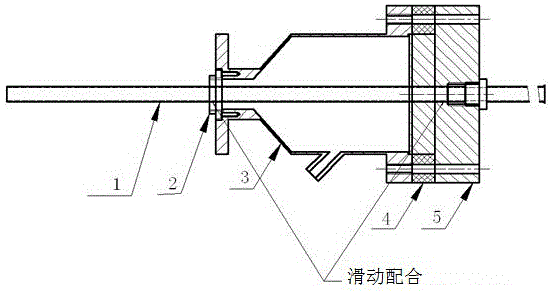
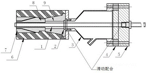
[0020] see figure 1 , figure 2 , image 3 , a dry-type optical fiber ribbon loose tube air blow molding device, the air blow molding device includes an extrusion device and an air blowing device, and the air blowing device includes an optical fiber ribbon conduit 1, a front positioning end cap 2, and an air blowing device tank body 3 , the rear positioning end cap 4 and the air supply assembly connected with the tank body of the air blowing device, the two ends of the tank body of the air blowing device are respectively provided with a front positioning end cap 2 and a rear positioning end cap 5, and the optical fiber ribbon conduit 1 runs through the entire Air-blowing device tank body; said extruding device comprises extruder head 6, extruder extruding outer mold 7, extruder extruding inner mold 8 and splitter cone 9, said extruder head 6 An extruder extruder outer mold 7 and an extruder inner extruder mold 8 are provided, and the extruder inner extruder mold 8 is arrange...
Embodiment 2
[0022] see figure 1 , figure 2 , image 3 , as an improvement of the present invention, the air blowing device further includes a polytetrafluoro gasket 4, and the polytetrafluoro gasket 4 is arranged between the tank body 3 of the air blowing device and the rear positioning end cap 5. This technical solution is equipped with a polytetrafluoroethylene gasket 4, which effectively plays a role of heat insulation and isolates the heat transmitted from the head of the extruder. And heat, avoiding the problem that the optical fiber ribbon is affected by high temperature before entering the machine head. The front and rear positioning end caps and the polytetrafluoro gasket 4 are connected with the tank body with countersunk bolts after being positioned by its flange surface. The dimensional tolerance of the optical fiber ribbon conduit is guaranteed to slide and fit with the front and rear end covers through processing, which is convenient for disassembly and assembly, and the ...
Embodiment 3
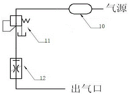
[0024] see figure 1 , figure 2 , image 3 , as an improvement of the present invention, the front positioning end cap is provided with an air outlet groove, which is convenient for gas to enter the gap between the splitter cone and the optical fiber ribbon conduit, and the air supply assembly includes an air source and a pipeline connected to the air source As well as the gas storage tank, pneumatic triple piece, filter and gas flow meter arranged on the pipeline, there is a gap between the splitter cone and the fiber optic ribbon conduit, and the extrusion inner mold of the extruder and the fiber optic ribbon conduit Set with gaps. The rest of the structures and advantages are exactly the same as in Embodiment 1.
PUM
 Abstract
Description
Claims
Application Information
 - R&D
- Intellectual Property
- Life Sciences
- Materials
- Tech Scout
- Unparalleled Data Quality
- Higher Quality Content
- 60% Fewer Hallucinations
Browse by: Latest US Patents, China's latest patents, Technical Efficacy Thesaurus, Application Domain, Technology Topic, Popular Technical Reports.
© 2025 PatSnap. All rights reserved.Legal|Privacy policy|Modern Slavery Act Transparency Statement|Sitemap|About US| Contact US: help@patsnap.com


