
Plastic pipe electric end bending machine

A technology of plastic pipe and edge bending machine, applied in the direction of tubular goods, other household appliances, household appliances, etc., can solve the problems of processing pipe length limitation, uneven welding, waste of energy, etc., to achieve rapid mass production, small equipment , easy to use effect

Active Publication Date: 2018-07-24
厦门中井科技有限公司
View PDF3 Cites 0 Cited by
  • Summary
  • Abstract
  • Description
  • Claims
  • Application Information

AI Technical Summary

Problems solved by technology

There are deficiencies in the purchase of this separate multi-step flanging method: 1. It needs three times of heating and three times of molding, which not only wastes energy, but also has low work efficiency; When forming on the mold, the temperature of the pipe material changes greatly, and it is also affected by the ambient temperature
Therefore, when flanges or flanging are formed on the end faces of pipes and fittings, flanging cracks are prone to occur, and it is difficult to ensure quality
3. Due to the separation and multi-step method, it is difficult to match the temperature of the pipe flanging and the deformation force applied during the flanging. It is easy to appear uneven thickness of the flanging mouth
[0004] Second, the existing structural type that adopts the flanging looper flange is that the flanging short joint of the flanging mouth formed by the injection molding machine is inserted into the looper flange, and then hot-melt welded on the pipe port, and then made The surrounding is fully welded and formed. This kind of processing is time-consuming and laborious, and the processing quality is often not guaranteed.
However, there are the following disadvantages: 1. The weld is generally welded on one side, the inner and outer walls cannot be formed on both sides, and the quality of welding is unreliable; 2. It must be a skilled worker, and the cost is high; 3. The surface of the welding connection point must be wiped clean when welding , so the product connection must be welded indoors to ensure the welding quality; 4. The equipment investment is high and the volume and weight are large, often the construction site cannot meet the above process requirements, and the site generally does not have pipeline solder joint flaw detection testing equipment. If it is poor, it will cause the pipe and flange to fall off under the state of conveying pressure flow
[0005] Third, at present, the connection between PE pipes needs to be connected by hot-melt butt welding. The butt joint can only be directly heated and welded at the pipe end. The thickness of the welded joint is actually only a few millimeters thick, and the welding requirements for the construction process are relatively high.
The disadvantage is that during welding, the operating pressure and temperature need to be very emphasized. Excessive force or high temperature will cause excessive melting of the pipe, and uneven weld bumps and seams will easily occur on the inner wall of the pipe, resulting in shrinkage and flow path. It becomes smaller, and at the same time, it is easy to produce defect areas of piled materials. After a long period of time, it is bound to form a dead angle at the hot-melt welding point and cause pipeline blockage
Disadvantages: 1. The welding quality is not easy to check, and it is easily affected by factors such as climate, environment, and human factors; 2. The investment in equipment is high and the volume and weight are large; 3. It is only suitable for the butt connection of pipe diameters larger than 110mm, and small diameters cannot Implement butt jointing; 4. The length of the processed pipe is limited by the tool; 5. The hot-melt butt joint connection is a fusion connection (also a rigid connection), and once it faces an earthquake, the fracture of the connection end is very serious, and the dislocation is easy to break
Disadvantages: 1. The welding quality is not easy to check, and it is easily affected by climate, environment, human factors and other factors; 2. The investment in equipment is high and the volume and weight are large; 3. It is only suitable for butt joints with pipe diameters larger than 110mm, and small diameters cannot be used for butt joints ; 4. The length of the processed pipe is limited by the tool, and the length can only be about a dozen centimeters, which is difficult to promote and use in a large area

Method used


Image

  • Plastic pipe electric end bending machine
  • Plastic pipe electric end bending machine

Examples


Embodiment Construction

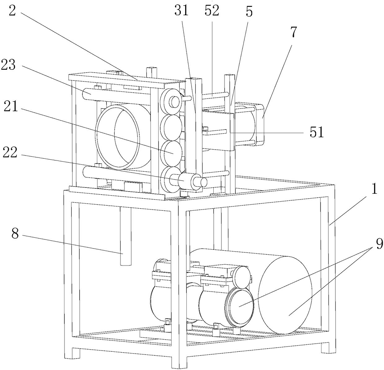
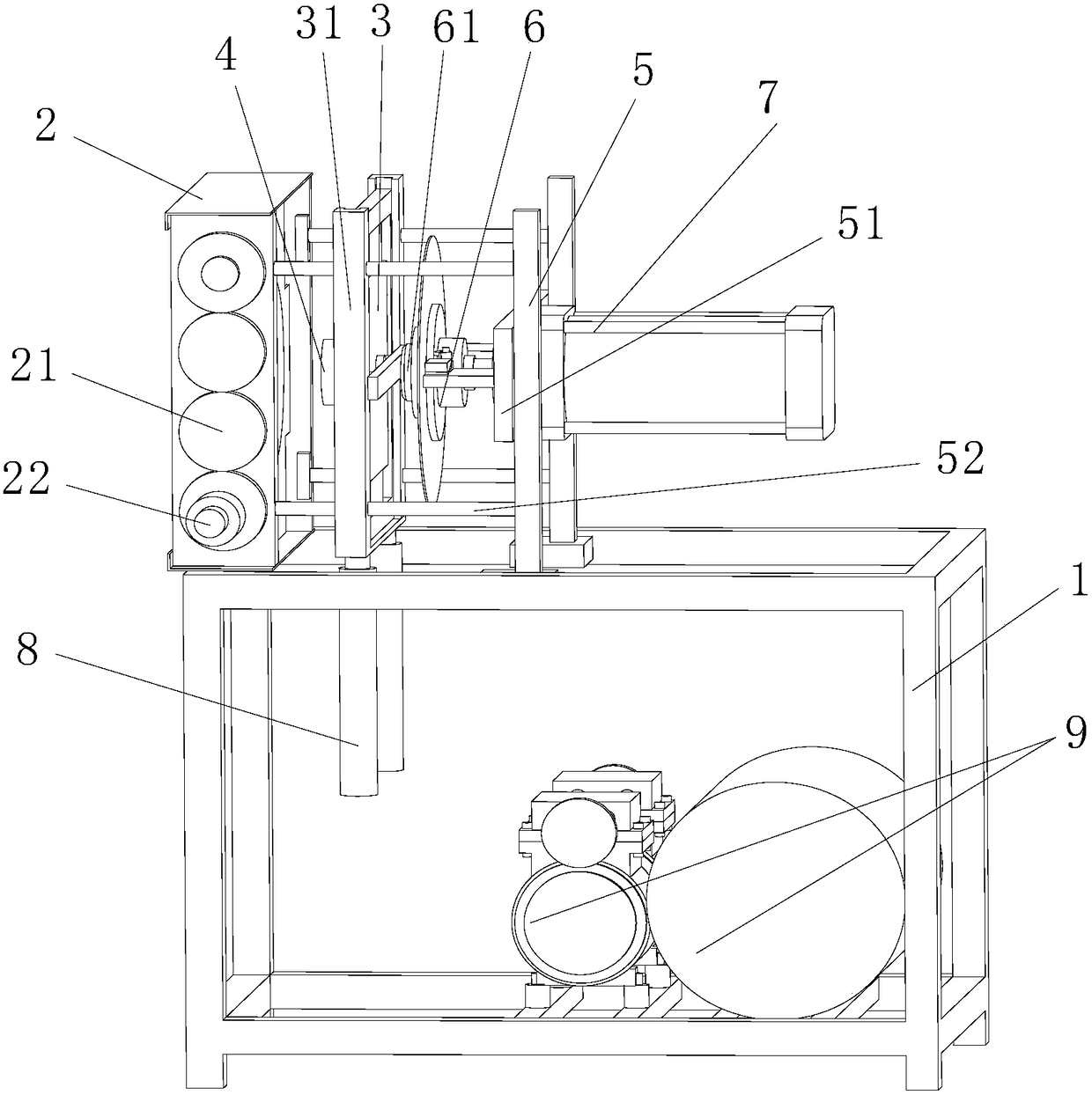
[0019] see figure 1 and 2 , the present embodiment is provided with machine base 1, fixture 2, heating plate 3, heating plate 4, slide rail device 5, extruded forming plate 6, first push-pull cylinder 7, second push-pull cylinder 8, air compressor 9 and cooling device .

[0020] The fixture 2 is installed on the machine base 1, the heating plate 4 and the heating plate 3 are arranged behind the fixture 2, the extruded forming plate 6 is arranged behind the heating plate 3, and the extruded forming plate 6 is provided with a lining head 61 and surrounding the lining head An annular groove for curved edge forming, the first push-pull cylinder 7 is installed on the base 1 through the slide rail device 5, the piston of the second push-pull cylinder 8 is connected with the bottom of the heating plate 3, the piston of the first push-pull cylinder 7 is connected with the bottom of the heating plate 3 The rear end of the extruded disk 6 is connected, and the extruded disk 6 is slida...


PUM


Abstract

The invention provides an electric end surface collaring machine for plastic pipes and relates to processing equipment for plastic pipes. The electric end surface collaring machine for plastic pipes has a simple portable structure, can be carried and used conveniently, cannot be influenced by construction environment in any occasion, is not limited by the length of a conveying pipe, and can process flanges, fold edges or integrated flanges and fold edges on the end surfaces of the pipes. The electric end surface collaring machine for plastic pipes is provided with a machine base, a clamp, a heating plate, a heating coil, a sliding rail device, an extrusion forming plate and a push-pull cylinder, wherein the clamp is arranged on the machine base; the heating plate and the heating coil are arranged behind the clamp; the heating coil is arranged at the center point of the heating plate and is used for heating the pipes; the heating plate slides in the sliding rail device; the extrusion forming plate is arranged behind the heating plate and is provided with an interlining and an annular groove surrounding the interlining for curve edge formation; the push-pull cylinder is arranged on the machine base; the piston of the push-pull cylinder is connected with the rear end of the extrusion forming plate; the piston of the push-pull cylinder is connected with the bottom of the heating plate; and the extrusion forming plate is in sliding fit with the heating plate by the sliding rail device.

Description

technical field [0001] The invention relates to a mobile processing equipment for plastic pipes and fittings, in particular to an electric end bending machine for plastic pipes which is suitable for flanging various thermoplastic pipes and is used to form flanges or flangings on the end faces of pipes and fittings. Background technique [0002] Plastic pipes are widely used, such as water supply and drainage pipes. As we all know, the products produced by plastic pipes are all straight pipes, and plastic pipes cannot produce products with curved edges (flanges) on the production line. Since each section of plastic pipe needs to be connected during construction, the current connection methods generally adopt the following schemes: [0003] First, the flanging device currently used for plastic pipes is a separate multi-step method, that is, the plastic pipe heating device is separated from the force-applying mechanism when flanging, and the implementation steps are multiple t...

Claims


Application Information

Patent Timeline
Patent Type & Authority Patents(China)
IPC IPC(8): B29C57/00B29L23/00
CPCB29C57/00B29L2023/00
Inventor 陈荣辉
Owner 厦门中井科技有限公司
Learn More