Steel quenching device

A quenching device, steel technology, applied in the direction of quenching device, heat treatment equipment, furnace, etc., can solve problems such as increasing production cost, multi-manpower, etc., and achieve the effect of fast work efficiency

Inactive Publication Date: 2016-06-15
魏会芳
View PDF4 Cites 0 Cited by
  • Summary
  • Abstract
  • Description
  • Claims
  • Application Information

AI Technical Summary

Problems solved by technology

[0002] Nowadays, with the development of society, the use of steel is increasing, and some users have certain requirements for the hardness of steel. Now most of the steel productio

Method used


Image

  • Steel quenching device

Examples


Embodiment Construction

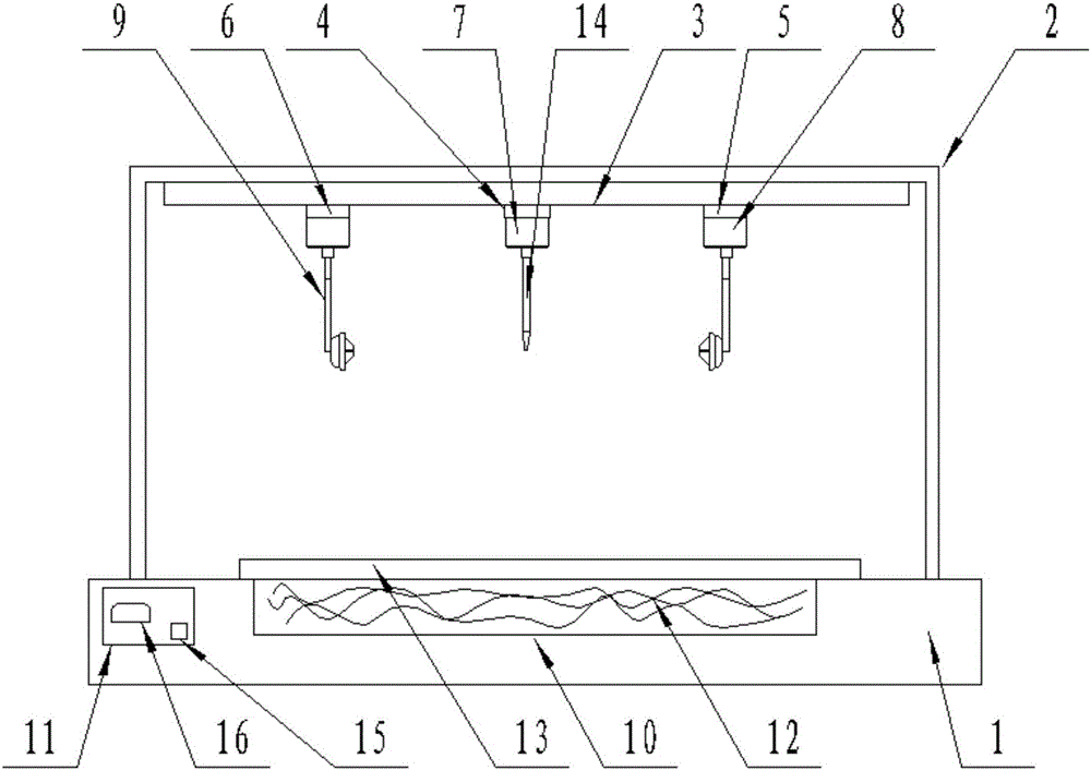
[0012] The present invention is specifically described below in conjunction with accompanying drawing, as figure 1 As shown, a steel quenching device includes a workbench (1), the workbench (1) is provided with a gantry (2), and the beam of the gantry (2) is provided with a slide rail (3) , the slide rail is provided with an electric slider (4), an electric slider A (5) and an electric slider B (6), and the electric slider (4) is located between the electric slider A (5) and the electric slider Between the blocks B (6), the lower surface of the electric slider (4) is provided with a linear cylinder A (7), and the lower surfaces of the electric slider A (5) and the electric slider B (6) are provided with a straight line Cylinder (8), described linear cylinder (8) is provided with manipulator (9), and described workbench (1) upper surface has extraction tank (10), and described workbench (1) side is provided with control device (11), the controller (11) is electrically connecte...


PUM


Abstract

The invention discloses a steel material quenching device, which comprises a workbench, a gantry is arranged on the workbench, a slide rail is arranged on the beam of the gantry, an electric slider, an electric slide Block A and electric slider B, the electric slider is located between the electric slider A and the electric slider B, the lower surface of the electric slider is provided with a linear cylinder A, the electric slider A and the electric slider B The lower surface is provided with a linear cylinder, and a manipulator is provided under the linear cylinder, an extraction tank is opened on the upper surface of the workbench, and a controller is provided on one side of the workbench, and the controller is connected with the electric slider, electric Slider A, electric slider B are electrically connected with a group of linear cylinders. The invention has the advantages of simple structure and strong practicability.

Description

technical field [0001] The invention relates to the field of steel material extraction, in particular to a steel material quenching device. Background technique [0002] Nowadays, with the development of society, the use of steel is increasing, and some users have certain requirements for the hardness of steel. Now most of the steel production plants in the world are using extraction, which requires a lot of manpower and improves production. Cost, in order to solve this kind of problem needs a kind of new equipment. Contents of the invention [0003] The purpose of the present invention is to solve the above problems, and a steel quenching device is designed. [0004] To achieve the above object, the technical solution of the present invention is a steel quenching device, including a workbench, a gantry is provided on the workbench, a slide rail is provided on the beam of the gantry, and a slide rail is provided in the slide rail. Electric slider, electric slider A and e...

Claims


Application Information

Patent Timeline
IPC IPC(8): C21D1/63C21D1/52C21D9/00
CPCC21D1/63C21D1/52C21D9/0062
Inventor 魏会芳董亚敏吕博鑫赵涛涛段刚李伟
Owner 魏会芳
Why Eureka
Try Eureka