Sealing structure for output shaft of wind power gear box

A wind power gearbox and sealing structure technology, applied in the direction of engine sealing, belt/chain/gear, transmission parts, etc., can solve the problems of fog beads, difficult processing and assembly, oil leakage and so on

Active Publication Date: 2016-06-15
CHONGQING WANGJIANG IND
View PDF6 Cites 3 Cited by
  • Summary
  • Abstract
  • Description
  • Claims
  • Application Information

AI Technical Summary

Problems solved by technology

Since there are many factors affecting the radial gap between the radial rear labyrinth seal 4 and the output shaft 2 and the end cover 1, the control is very difficult, the requirements for processing and assembly are very high, and processing and assembly is difficult
[0004] 2. There is only a single radial rear labyrinth seal 4, and the length controlled by the radial gap between the end cover 1 and the radial rear labyrinth seal 4 is two shorter sections. When the output shaft 2 is running at high speed , due to the large pressure difference between the inside and outside of the gear case 5, the lubricating oil may be thrown out along the right end of the radial rear labyrinth seal 4, causing seepage and oil leakage, poor sealing effect, high reliability and safety Low and low service life
[0005] 3. The oil return channel D is shared, which may easily cause poor oil return. When the gearbox is running, because the internal oil temperature is higher than the ambient temperature, a pressure difference will be formed inside and outside the gearbox, and the oil return channel D is shared. The maximum pressure difference Directly to the outside, its oil vapor can easily seep directly to the outer wall through the gap, and after contacting the temperature of the outside world, it will form mist beads, which will form oil leakage over time.

Method used


Image

  • Sealing structure for output shaft of wind power gear box
  • Sealing structure for output shaft of wind power gear box

Examples


Embodiment Construction

[0018] Below in conjunction with accompanying drawing, the present invention is described in further detail;

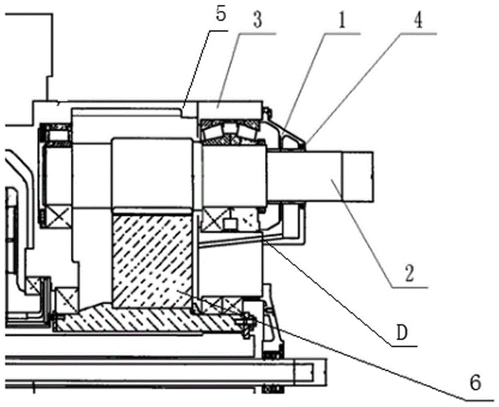
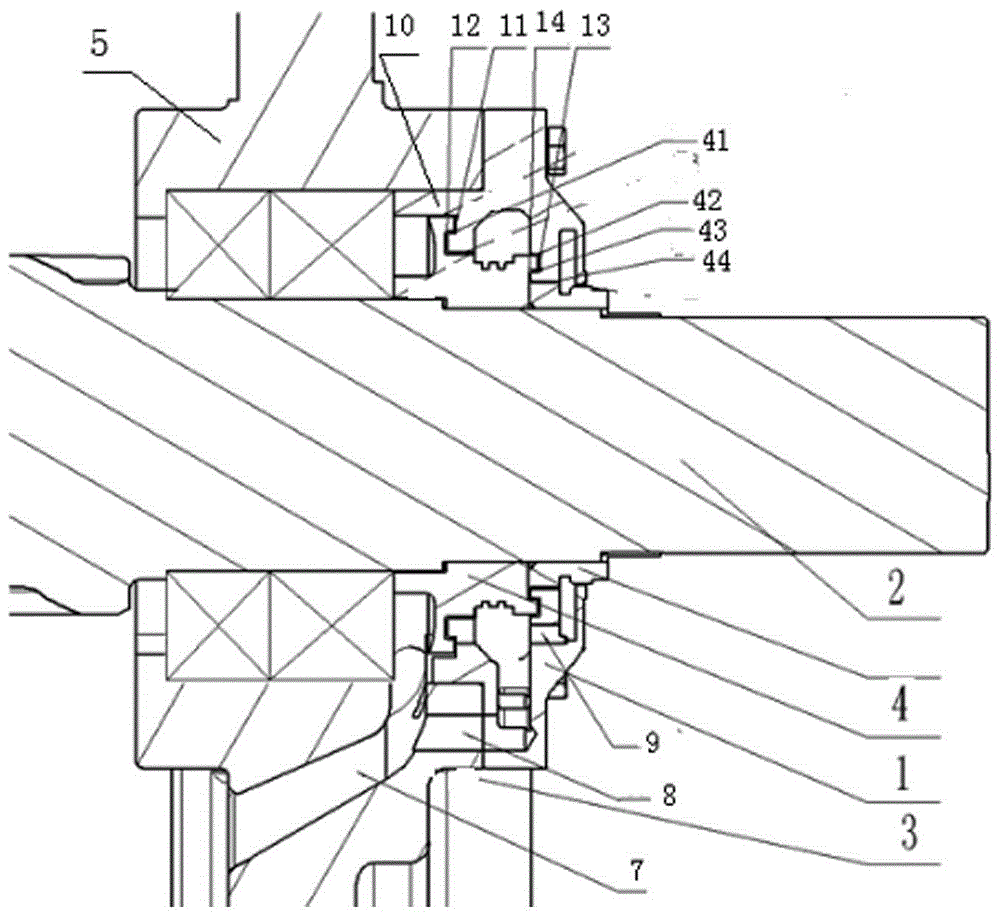
[0019] see figure 2 , the wind power gearbox output shaft sealing structure, including; the left end is connected with the right end of the gear box body, the right end is connected with the left end of the rear box body 3, and the output shaft end cover 1 is connected with the left end and the right end of the rear box cover 5 , located in the inner oil pool of the gear case and the left end is assembled on the gear case, the right end passes through the output shaft 2 outside the rear case body 3, the rear case cover 5 and the output shaft end cover 1, and is located in the rear case body 3 The oil pool and the oil return passage D of the output shaft end cover 1 are communicated with each other, and a radial rear labyrinth seal 4 is arranged between the output shaft 2 and the output shaft end cover 1 . from figure 2 It can be seen that the present invention als...


PUM


Abstract

The invention provides a sealing structure for an output shaft of a wind power gear box. The sealing structure is characterized by further comprising an end surface maze type seal which is connected to an output shaft end cover (1), wherein the end surface maze type seal comprises a body (10) and first, second, third, and fourth sealing end surfaces (11), (12), (13) and (14) arranged on the body; the first, second, third, and fourth sealing end surfaces are arranged from outside to inside in a radial direction, and are arranged from left to right in an axial direction; and correspondingly, first, second, third and fourth sealing end surfaces (41), (42), (43) and (44) which are in sealing fit with the first, second, third and fourth sealing end surfaces of the end surface maze type seal separately are arranged on a radial rear maze type seal (4).

Description

technical field [0001] The invention relates to a sealing structure of a wind power gearbox, in particular to a sealing structure of an output shaft of a wind power gearbox. Background technique [0002] The traditional wind power gearbox output shaft seal structure, see figure 1 , including; the rear case cover 5 whose left end is connected with the right end of the gear box body, the right end is connected with the left end of the rear case body 3, the output shaft end cover 1 whose left end is connected with the right end of the rear case cover 5, and is located in the inner oil of the gear case body In the pool 6 and the left end is assembled on the gear box, the right end passes through the output shaft 2 outside the rear box body 3, the rear box cover 5 and the output shaft end cover 1, and is located on the rear box body 3 and communicates with the oil pool 6 and the The oil return channel D of the output shaft end cover 1 is provided with a radial rear labyrinth sea...

Claims


Application Information

Patent Timeline
Patent Type & Authority Applications(China)
IPC IPC(8): F16H57/021F16H57/029F16J15/447
CPCF16H57/021F16H57/029F16J15/4476F16H37/041F03D15/00F05B2240/57
Inventor 张鑫柯萍赖东曹杰
Owner CHONGQING WANGJIANG IND
Why Eureka
Try Eureka