Humidifier and air treatment device

A humidification device and water tank technology, applied in lighting and heating equipment, valve devices, mechanical equipment, etc., can solve the problems of short life of the water curtain, high power consumption, easy to produce white powder, etc., to achieve convenient installation and use, and improve the use of The effect of life and long service life

Inactive Publication Date:
View PDF4 Cites 4 Cited by
  • Summary
  • Abstract
  • Description
  • Claims
  • Application Information

AI Technical Summary

Problems solved by technology

[0003] In order to solve the problems of indoor air dryness and poor cleanliness, there are currently three humidification methods on the market: electric heating humidification, ultrasonic humidification, and water evaporation humidification
Electric heating technology consumes a lot of power and will generate scale, while ultrasonic technology is prone to white powder
Although water evaporative humidification does not have the above two disadvantages, the existing evaporative humidification device, the water curtain is mostly soaked in water, the life of the water curtain is short and it is easy to accumulate impurities in the water, which affects the water absorption of the water curtain
[0004] Therefore, in order to solve the problems of scale generated by electric heating, white powder generated by ultrasonic waves and poor working effect of water evaporation water curtain, it is necessary to provide a humidifying device and air treatment device that is environmentally friendly, has a long service life, and has a variety of combined functions.

Method used


Image

  • Humidifier and air treatment device
  • Humidifier and air treatment device
  • Humidifier and air treatment device

Examples


Embodiment 1

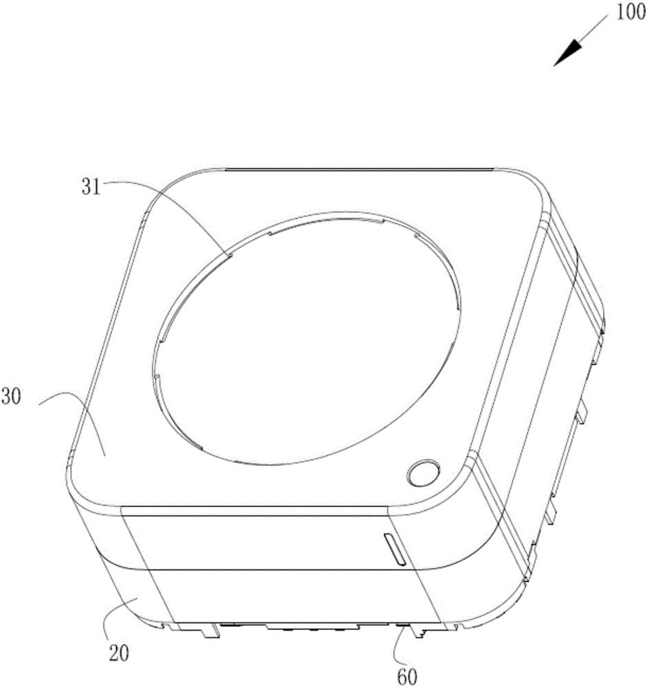
[0036] figure 1 A schematic diagram of an overall structure of a humidifying device 100 provided by an embodiment of the present invention is shown.

[0037] The water tank shell 30 and the base 20 constitute the appearance of the humidifier 100 , and the water tank shell 30 is arranged on the base 20 . The bottom of the base 20 is provided with a grid fixing plate 60 , and the top of the water tank shell 30 is provided with an air outlet 31 , the humidifier 100 enters the air through the grid fixing plate 60 , and the air flows through the inside of the humidifier 100 to bring mist out from the air outlet 31 .

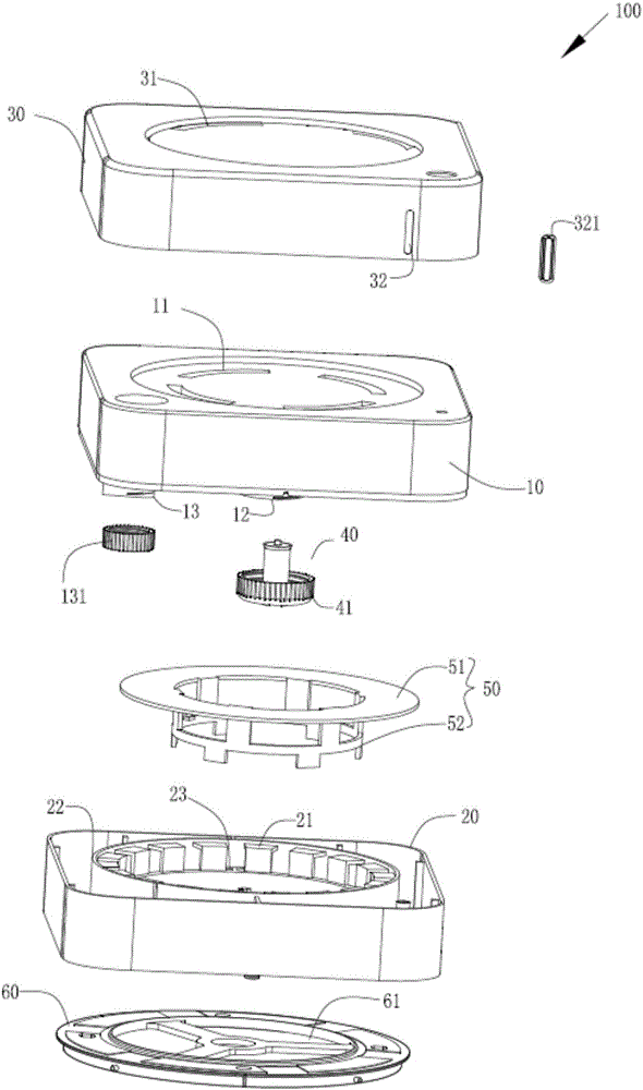
[0038] figure 2An exploded schematic diagram of a humidifying device 100 provided by an embodiment of the present invention is shown.

[0039] The humidifier 100 includes a water tank 10 , a base 20 and a water curtain 21 . In the present embodiment, the water tank 10 is square and made of transparent material. The top of the water tank 10 is provided with at lea...


PUM


Abstract

The invention provides a humidifier and an air treatment device. The humidifier comprises a water tank, a base and a water curtain, wherein the water tank is arranged on the base; the water curtain is arranged in the base; the humidifier also comprises a water control valve; the water control valve is connected with the water tank and stretches into the base; the height of the bottom surface of the water control valve is greater than the height of the bottom surface of the water curtain; at least one air inlet is formed at the bottom of the base; at least one air outlet is formed at the top of the water tank; each air inlet and each air outlet are communicated through the water curtain; when the water level in the base is higher than the bottom surface of the water control valve, the water control valve does not discharge water; when the water level in the base is lower than the bottom surface of the water control valve, the water control valve discharges water; the air treatment device comprises the humidifier, an unpowered fan and an air source device; and the unpowered fan is positioned between the humidifier and the air source device. The humidifier and air treatment device provided by the invention have the advantages of simple structure, convenience in mounting and use, environmental protection, energy conservation and long service life.

Description

technical field [0001] The invention relates to the field of air treatment, in particular to a humidifier and air treatment equipment. Background technique [0002] In daily life, the indoor air is often relatively dry, especially in the autumn and winter seasons. The dry air makes the human body feel uncomfortable. The air humidity index and cleanliness index are directly related to people’s health. Therefore, the indoor air Humidification and treatment are necessary. [0003] In order to solve the problems of indoor air dryness and poor cleanliness, there are currently three humidification methods on the market: electric heating humidification, ultrasonic humidification, and water evaporation humidification. Electric heating technology consumes a lot of power and produces scale, while ultrasonic technology is prone to white powder. Although water evaporative humidification does not have the above two disadvantages, most of the water curtains are immersed in water in the ...

Claims


Application Information

Patent Timeline
Patent Type & Authority Applications(China)
IPC IPC(8): F24F6/04F24F11/00F16K21/18
CPCF16K21/18F24F6/043F24F2006/001F24F11/70F24F11/84F24F8/10F24F8/117
Inventor 熊智文方思达林香泉
Why Eureka
Try Eureka