Heat pump type waste heat utilization inertial dust collection penetrating countercurrent drying machine

A dryer and heat pump technology, which is applied in the field of heat pump tail heat using inertial dust removal to penetrate countercurrent dryers, can solve problems such as difficulty in disassembly, and achieve the effects of eliminating fatigue fractures, strong extrusion rigidity, and enhanced bearing capacity

Active Publication Date: 2016-06-15
四川良仕农业科技有限公司
View PDF6 Cites 4 Cited by
  • Summary
  • Abstract
  • Description
  • Claims
  • Application Information

AI Technical Summary

Problems solved by technology

In the actual assembly of shafts and holes with transmission threads, in order to achieve large load-bearing functions, the size of the threaded shafts and matching nut-like components are relatively large, and it is often easy and convenient to screw in during assembly, and It can realize the automatic and continuous locking of the bearing capacity during use, so it is very reliable, but when it is disassembled, the assembly is often very tight, and disassembly is very difficult. It is particularly important to realize simple and easy disassembly under this condition

Method used


Image

  • Heat pump type waste heat utilization inertial dust collection penetrating countercurrent drying machine
  • Heat pump type waste heat utilization inertial dust collection penetrating countercurrent drying machine
  • Heat pump type waste heat utilization inertial dust collection penetrating countercurrent drying machine

Examples


Embodiment Construction

[0031] Now in conjunction with accompanying drawing, the present invention is described in further detail.

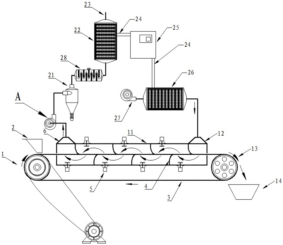
[0032] Such as figure 1 , figure 2 , image 3 , Figure 4 , Figure 5 , Figure 6 , Figure 7 , Figure 8 with Figure 9 The shown heat pump tail heat penetrates the countercurrent dryer by using inertial dust removal, including the dryer cabinet 11 and the induced draft fan A. The two ends of the dryer cabinet 11 are respectively provided with an exhaust hood 6 and an air inlet hood 12, and the exhaust hood 6 is connected to The induced draft fan A is emptied after being connected to the evaporator 22 of the heat pump system through the cyclone dust collector 21 and the repeatedly turning baffle type inertial dust collector 28; the evaporator 22 of the heat pump system is connected to the main engine 25 through the refrigerant pipe 24, and the main engine 25 The refrigerant pipe 24 is connected to the condenser 26; the air outlet end of the blower 27 is connec...


PUM


Abstract

The invention discloses a heat pump type waste heat utilization inertial dust collection penetrating countercurrent drying machine. An exhaust hood of the drying machine is connected with an induced draught fan. The induced draught fan is evacuated after being connected with an evaporator of a heat pump system through a cyclone dust collector and a repeated back-turning baffle type inertial dust collector. The evaporator of the heat pump system is connected with a main machine through a refrigerant pipe. The main machine is connected with a condenser through a refrigerant pipe. The air outlet end of an air blower is connected in an air inlet hood through the condenser. Blades of an impeller of the induced draught fan are arranged to be in a radial shape and centrosymmetric about an impeller shaft in the radial direction, dust can be removed in time under the effect of centrifugal force, and safety accidents are avoided. The drying efficiency is improved, energy conservation and emission reduction are achieved, more importantly, a demounting and mounting technology of the induced draught fan is transformed to a great extent, when the induced draught fan is demounted, the pressure applied to the end face of a screw shaft shoulder by nut-like parts can be simply eliminated, the problem that the induced draught fan assembled in a threaded manner is automatically locked continuously under the effect of loads and cannot be easily demounted is effectively solved, the heat pump type waste heat utilization inertial dust collection penetrating countercurrent drying machine is particularly suitable for convenient demounting of large draught fans which are locked in a threaded manner, and effects are particularly obvious.

Description

technical field [0001] The invention relates to a drying machine, which specifically refers to a heat pump tail heat penetrating counter-current drying machine which uses inertial dust removal and is easy to disassemble and repair. Background technique [0002] People generally refer to drying with a drying temperature below 60 degrees Celsius as low-temperature drying. Low-temperature drying is widely used in the drying of heat-sensitive materials such as crop seeds, Chinese medicinal materials, and biological products. Due to its mature technology, strong adaptability, low operating cost and high reliability, hot air dryer is still one of the first choice equipment for low temperature drying. Low-temperature drying is less likely to utilize tail heat due to the lower temperature of exhaust gas. If the penetration and countercurrent drying of materials can be realized in the hot-air low-temperature drying process, and the tail heat can be effectively recovered, it will be ...

Claims


Application Information

Patent Timeline
Patent Type & Authority Applications(China)
IPC IPC(8): F26B15/18F26B21/00F26B21/04F04D17/16F04D29/28F04D29/30F04D29/26F04D29/054
CPCF04D17/16F04D29/054F04D29/263F04D29/281F04D29/30F26B15/18F26B21/001F26B21/04
Inventor 王光忙银永忠
Owner 四川良仕农业科技有限公司
Why Eureka
Try Eureka