
Eddy current flaw detection device and bearing detector using same

A detection device and eddy current flaw detection technology, which is used in measurement devices, mechanical bearing testing, instruments, etc., can solve the problems of complex positioning mechanism, reduced detection efficiency, detection head damage, etc., to achieve high adjustment accuracy, improve detection efficiency, and improve adaptability sexual effect

Active Publication Date: 2016-06-15
淮安辰锟科技有限公司
View PDF9 Cites 16 Cited by
  • Summary
  • Abstract
  • Description
  • Claims
  • Application Information

AI Technical Summary

Problems solved by technology

[0004] In the existing technology, the traditional bearing flaw detection method is to use magnetic powder for flaw detection. This flaw detection method is not environmentally friendly due to large pollution. Therefore, a new flaw detection method has emerged, which uses eddy current flaw detection to detect the axial flaw. , but in actual use, most of the eddy current flaw detection needs to use a special detection head. During the detection, the detection head needs to be in contact with the outer peripheral surface of the bearing. The detection head is easy to cause damage during the detection. The detection device of the existing automatic detection machine needs the cylinder to drive the front roller to move when positioning, so that the bearing to be tested can be clamped between the front roller and the rear roller to realize the bearing. Positioning, the positioning mechanism is complicated and the steps are numerous, which reduces the detection efficiency

Method used


Image

  • Eddy current flaw detection device and bearing detector using same
  • Eddy current flaw detection device and bearing detector using same
  • Eddy current flaw detection device and bearing detector using same

Examples


Embodiment Construction

[0038] The present invention will be described in further detail below in conjunction with the accompanying drawings.

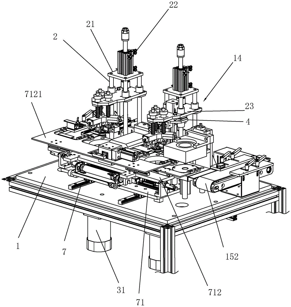
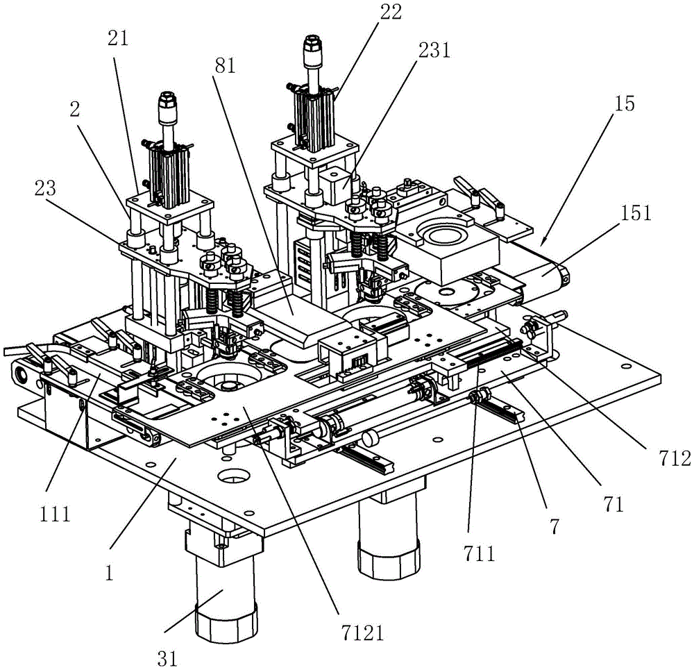
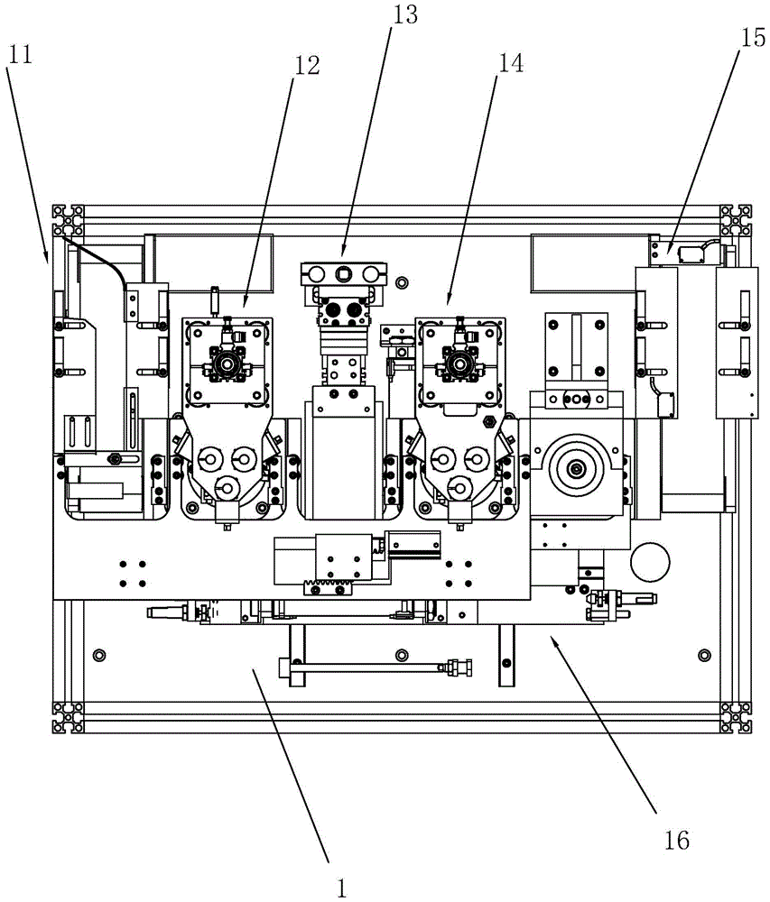
[0039]An eddy current flaw detection device, comprising a workbench 1, on which a pan plate 3 for placing a bearing 9 to be tested is rotated, and a drive motor 31 is provided at the bottom of the workbench 1 to drive the pan plate 3 to rotate, The output shaft of the driving motor 31 is connected with the flat rotating plate 3, and an annular groove 32 is arranged on the flat rotating plate 3. The bearing is placed at the center position of the flat rotating plate 3, and the annular groove 32 is set. When the detection head 61 moves to the outermost position of the outer ring At the lower end, the annular groove 32 can prevent the detection head 61 from colliding with the pan plate 3. After the bearing 9 to be detected is pressed on the pan plate 3, the drive motor 31 drives the pan plate 3 to rotate, and the detection head 61 is vertically synchronized. Mov...


PUM


Abstract

The invention discloses an eddy current flaw detection device and a bearing detector using the same.The technical scheme mainly includes that the eddy current flaw detection device comprises a worktable, a flat rotation plate for holding bearings to be detected is arranged on the worktable rotatably, an arrangement block is arranged above the flat rotation plate on the worktable in a slipping manner, supports forming 120 degrees with one another are arranged on the arrangement block in a circumferential array manner, a positioning wheel is arranged at the bottom of every support rotatably and is arranged on the corresponding support by inclining towards, and a detection head which can butt against one bearing is arranged above the flat rotation plate of the worktable in a slipping manner.The eddy current flaw detection device and the bearing detector have the advantages that the three positioning wheels form 120 degrees with one another, and the bearings can be automatically positioned in the center of the arrangement block through the positioning wheels to achieve centering of the bearings to the detected automatically, so that the detection device is structurally simplified, detection steps are decreased and detection efficiency is improved.

Description

technical field [0001] The present invention relates to a peripheral part flaw detection equipment, more specifically, it relates to an eddy current flaw detection detection device and a bearing detection machine using the device. Background technique [0002] In the manufacturing process of the bearing, it is necessary to detect the hardness of the inner and outer rings of the bearing and the cracks of the inner and outer rings of the bearing, that is, to detect the flaw detection hardness of the bearing. The flaw detection hardness of the existing bearing is usually tested by hardness testing equipment and flaw detection equipment. Manual inspection is inefficient and labor-intensive. In manual inspection, due to the influence of human factors, the detection range is not comprehensive, and there will be detection blind spots, which affects the quality of bearing inspection. [0003] Therefore, the invention patent with the publication number: CN105158329A provides a fully ...

Claims


Application Information

Patent Timeline
IPC IPC(8): G01N27/90G01M13/04G01N27/9013
CPCG01M13/04G01N27/9006
Inventor 朱微
Owner 淮安辰锟科技有限公司
Learn More