

Developing box
A developing cartridge and developing unit technology, applied in the field of developing cartridges, can solve the problems of unfavorable developing quality, improvement, uneven rotation speed of developing roller, etc., and achieve the effect of improving developing quality and reducing manufacturing cost
- Summary
- Abstract
- Description
- Claims
- Application Information
AI Technical Summary
Problems solved by technology
Method used
Image

Examples
no. 1 example
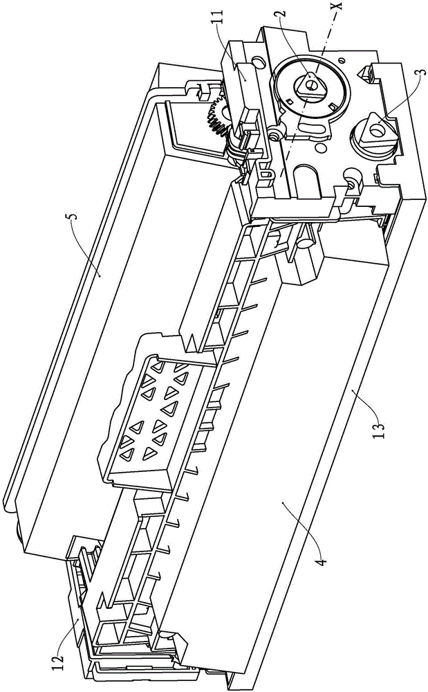
[0037] see figure 1 , The developing cartridge is driven by the drive end cover 11, the conductive end cover 12, the photosensitive drum protective cover 13, the torque spring, the drum rotation force receiver 3, the drum unit 4, the developing unit 5 and the development rotation force receiver 2. Switch unit configuration. The drive end cover 11 and the conductive end cover 12 constitute the box body of this embodiment, and the developing rotational force receiver 2 can rotate around the rotation axis X.
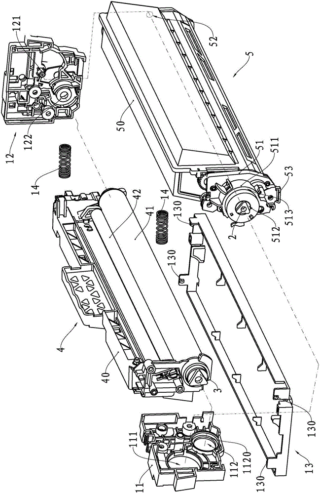
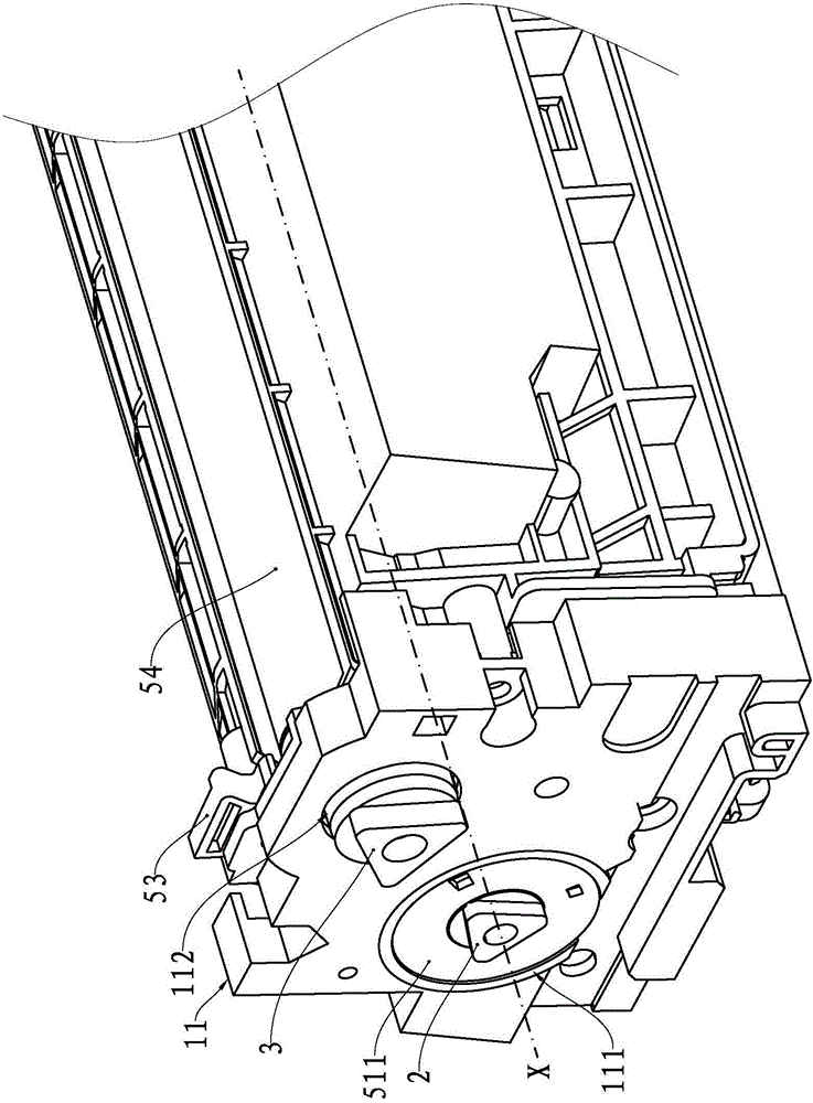
[0038] see figure 2 and image 3 , The driving end cover 11 is provided with a supporting shaft hole 111 and a shaft hole 112 , and an inner shaft shoulder 1120 is formed in the supporting shaft hole 111 . The conductive end cover 12 is provided with a support post 121 and a pin hole 122 .
[0039] The photosensitive drum protection cover 13 is detachably fastened on the box body by buckle 130 and the snap-in slots provided on the upper drive end cover 11 and the cond...
no. 2 example
[0060] As an explanation of the second embodiment of the present invention, only the differences from the first embodiment will be described below.
[0061] see Figure 12 In this embodiment, the first magnetic block 7631 and the second magnetic block 7632 are used to replace the spring to form the reset member of this embodiment, and both the first magnetic block 7631 and the second magnetic block 7632 are in a ring structure.
[0062] The necked end portion 7220 of the guide rod 722 passes through the inner holes of the first magnetic block 7631 and the second magnetic block 7632 in sequence, and then fits with the guide hole 7644 in a clearance.
[0063] The first magnetic block 7631 is fixed on the large-diameter end surface of the circular boss structure 720 by bonding, the second magnetic block 7632 is fixed on the bottom surface of the first receiving cavity 7640 by bonding, and the first magnetic block 7631 It is arranged opposite to the second magnetic block 7632 wit...
no. 3 example
[0066] As an explanation of the third embodiment of the present invention, only the differences from the first embodiment will be described below.
[0067] see Figure 13 The outer wall of the guide rod 822 protrudes laterally to form two round rods 8232 to replace the ring body in the first embodiment to form the output arm of this embodiment. The ring body 8641 is formed by protruding in the direction of the ring body 8641. Two notches 8642 matching the round rod 8232 are formed on the ring body 8641 along the direction parallel to the rotation axis X. The ring body 8641 with the notch 8642 replaces the first embodiment. The protrusion at the bottom of the first receiving chamber 8640 constitutes the input arm of this embodiment.
[0068] The upper end surface of the spring 863 abuts against the round rod 8232 instead of the large-diameter end surface of the circular boss structure 820 .
PUM
 Abstract
Description
Claims
Application Information