Electromagnetically controlled display device

A display device and electromagnetic control technology, applied in the direction of identification devices, instruments, etc., can solve the problems of large power consumption, canvas consumption, and manual replacement of patterns with three flaps

Inactive Publication Date: 2016-06-15
张清华
View PDF0 Cites 6 Cited by
  • Summary
  • Abstract
  • Description
  • Claims
  • Application Information

AI Technical Summary

Problems solved by technology

[0002] Current display devices are divided into self-luminous display devices and reflective display devices. Self-luminous display devices use self-luminous methods to display patterns, such as LED displays, liquid crystal displays, plasma displays, projectors, etc. Self-luminous display devices have The advantages of fast response and good image effect, but there are the following defects: 1. The device is expensive and requires a lot of power consumption; 2. Under strong outdoor light, more expensive light sources and electric energy are required; 3. Self-illumination The light is unnatural and uncomfortable for human eyes
The three flaps of the reflective display device use the hinge to flip the triangular prism to realize the pattern transformation, which has the advantage of low cost, but in practical application, we found that there are still the following defects: 1. The three flaps can only display 3 patterns at most; 2. The pattern of the three flaps depends on the inkjet canvas, so the canvas needs to be consumed every time the pattern is changed; 3. The pattern of the three flaps needs to be replaced manually; 4. For super large screens, transportation and installation are very troublesome; 5. Requires an external light source at night
In addition, self-luminous display devices and reflective display devices each have their own advantages and disadvantages, and there is currently no display device that combines the two.

Method used


Image

  • Electromagnetically controlled display device
  • Electromagnetically controlled display device
  • Electromagnetically controlled display device

Examples


Embodiment Construction

[0058] The present invention will be described in further detail below in conjunction with the accompanying drawings, but this description will not constitute a limitation to the present invention.

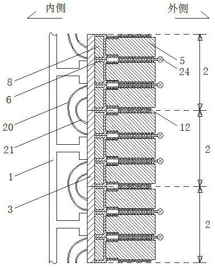
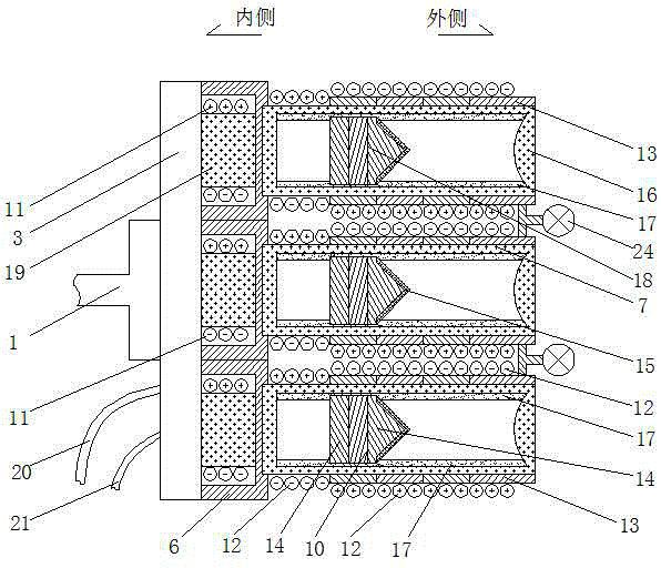
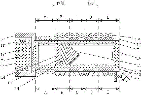
[0059] 1. If figure 1 Shown is a structural cross-sectional view of Embodiment 1 of an electromagnetically controlled display device of the present invention, figure 2 A cross-sectional view of the structure of the display unit shown in Embodiment 1 of the present invention, image 3 Shown is a sectional view of the structure of the electromagnetic color display tube of Embodiment 1 of an electromagnetically controlled display device of the present invention, which includes a frame 1 and several display units 2, and the display unit includes an integrated circuit board 3 and 3 electromagnetic color display tubes 5. It is characterized in that: the electromagnetic color display tube 5 includes a base 6, a hollow tube 7, a fixed magnet 8, a moving soft magnet 9, a lubricating mate...


PUM


Abstract

The present invention provides a display device that can replace patterns manually, does not consume canvas, is convenient to transport and install, low in price, low in energy consumption, natural and comfortable in light, and adopts electromagnetic control. The technical solution adopted is: The outer surface of the wall is coated with several groups of ring-shaped color layers in order, and several groups of soft magnetic electromagnetic coils are wound around the hollow tube and correspond to the positions of the ring-shaped color layers one by one. The direction of the magnetic field of the fixed magnet electromagnetic coil in the fixed magnet is the same or opposite, so as to control the moving position of the moving soft magnet in the hollow tube, and then affect the reflection position of the reflective material layer on the outside of the moving soft magnet to the incident light, so that the electromagnetic color can be displayed The color of the tube is changed, and the purpose of displaying the pattern is realized through an array of several electromagnetic color display tubes.

Description

technical field [0001] The present invention relates to display devices using electromagnetic control. Background technique [0002] Current display devices are divided into self-luminous display devices and reflective display devices. Self-luminous display devices use self-luminous methods to display patterns, such as LED displays, liquid crystal displays, plasma displays, projectors, etc. Self-luminous display devices have The advantages of fast response and good image effect, but there are the following defects: 1. The device is expensive and requires a lot of power consumption; 2. Under strong outdoor light, more expensive light sources and electric energy are required; 3. Self-illumination The light is unnatural and uncomfortable for human eyes. A reflective display device is a reflective display device, such as a three-flap panel. Reflective display devices have the advantages of being more natural and friendly than self-luminous display devices. The three flaps o...

Claims


Application Information

Patent Timeline
Patent Type & Authority Applications(China)
IPC IPC(8): G09F9/37
CPCG09F9/375
Inventor 不公告发明人
Owner 张清华
Why Eureka
Try Eureka