Motor assembly and vehicle starter

A technology of motor components and starters, which is applied in the direction of electric components, motor starters for engines, machines/engines, etc., to achieve the effect of avoiding wear

Inactive Publication Date: 2016-06-15
SEG AUTOMOTIVE GERMANY GMBH
View PDF4 Cites 5 Cited by
  • Summary
  • Abstract
  • Description
  • Claims
  • Application Information

AI Technical Summary

Problems solved by technology

[0006] This application aims to solve the problems caused by the axial play of the armature shaft of the electric motor in the prior art vehicle starter

Method used


Image

  • Motor assembly and vehicle starter
  • Motor assembly and vehicle starter
  • Motor assembly and vehicle starter

Examples


Embodiment Construction

[0024] Some preferred embodiments of the present application will be described below with reference to the accompanying drawings.

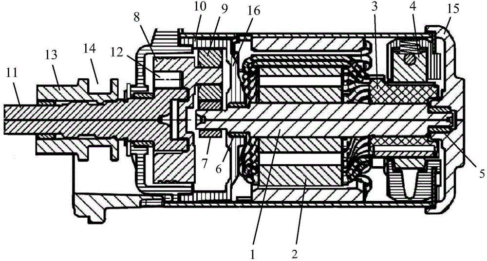
[0025] first, figure 1 A part of the vehicle starter of the present application is shown in , which mainly includes a motor assembly, a transmission mechanism and an electromagnetic switch, wherein the main components of the motor assembly and transmission mechanism are shown, and the electromagnetic switch is not shown.

[0026] The motor assembly is mainly composed of two parts, the motor and the speed change mechanism (reduction mechanism here). The motor mainly includes: an armature shaft 1; an armature winding 2 installed on the armature shaft 1; a commutator (commutator ) 3; push against the carbon brush 4 for power supply on the outer periphery of the commutator 3 .

[0027] The armature shaft 1 is supported at its axial ends by bearings 5, 6, respectively. Specifically, the rear portion of the armature shaft 1 is supported by a bearing ...


PUM


Abstract

The invention discloses a motor assembly, in particular a motor assembly of a vehicle starter. The motor assembly comprises a motor and a speed change mechanism, wherein the motor comprises an armature shaft; the speed change mechanism comprises an input gear; the input gear is arranged on the armature shaft through a spline; the spline comprises outer spline teeth and inner spline teeth; the outer spline teeth are formed on the armature shaft; the inner spline teeth are formed in the input gear and engaged with the outer spline teeth; and at least one of a pair of tooth side surfaces of each spline tooth inclines relative to the central axis of the armature shaft. The invention further discloses the vehicle starter comprising the motor assembly. A commutator and an electric brush of the motor can be prevented from being worn due to axial endplay of the armature shaft.

Description

technical field [0001] The present application relates to an electric motor assembly, which is particularly suitable for use in a vehicle starter; the present application also relates to a vehicle starter comprising such an electric motor assembly. Background technique [0002] The starter of a motor vehicle usually includes a DC motor, which is used to transmit the output motion of the motor to the transmission mechanism of the engine, and an electromagnetic switch to control the action of the motor and the transmission mechanism. [0003] Between the motor and the transmission mechanism, a gear reduction mechanism is generally arranged so that the starting power output by the transmission mechanism to the engine has low rotational speed and high torque. The input gear of the gear reduction mechanism is mounted on the armature shaft of the motor through a spur spline. The armature shaft is supported by bearings at both axial ends thereof. Typically, the armature shaft has...

Claims


Application Information

Patent Timeline
Patent Type & Authority Applications(China)
IPC IPC(8): H02K7/10H02K7/116F02N11/00
CPCF16H2057/02034F02N15/006F02N15/023F02N15/046F16D1/112F16H57/08F16H57/0025F16H57/022H02K7/116H02K7/118F16D2001/103F16D1/0882
Inventor 蒋佳佳
Owner SEG AUTOMOTIVE GERMANY GMBH
Why Eureka
Try Eureka