Speed regulation device and speed regulation method of DC brush motor

A technology of brushed DC motor and speed control device, which is applied in the direction of excitation or armature current control, and can solve the problems of increasing costs

Inactive Publication Date: 2016-06-15
JIANGSU REYA ELECTRIC
View PDF7 Cites 9 Cited by
  • Summary
  • Abstract
  • Description
  • Claims
  • Application Information

AI Technical Summary

Problems solved by technology

At present, the speed detection of brushed motors mainly uses methods such as tachogenerators, photoelectric encoders, and Hall sensors. These methods usually require additional equipme

Method used


Image

  • Speed regulation device and speed regulation method of DC brush motor
  • Speed regulation device and speed regulation method of DC brush motor
  • Speed regulation device and speed regulation method of DC brush motor

Examples


Embodiment 1

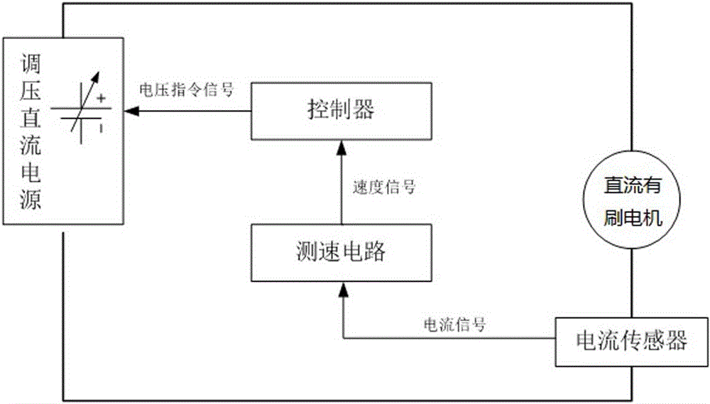
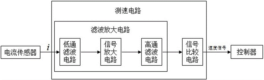
[0045] Such as figure 1 with image 3 As shown, the DC brushed motor speed control device of the present invention includes an adjustable power supply, and a DC brushed motor and a current sensor are sequentially connected in series between the positive terminal and the negative terminal of the adjustable power supply through wires. The current sensor is connected with a speed measuring circuit through a wire, the speed measuring circuit is connected with a controller through a wire, and the controller is connected with the adjustable power supply through a wire. The speed measurement circuit includes a filter amplifier circuit and a signal comparison circuit, the filter amplifier circuit and the signal comparison circuit are connected through wires, the filter amplifier circuit is connected with the current sensor through wires, and the signal comparison circuit is connected with the controller through wires. The controller has a built-in logical operation unit.

[0046] Wh...

Embodiment 2

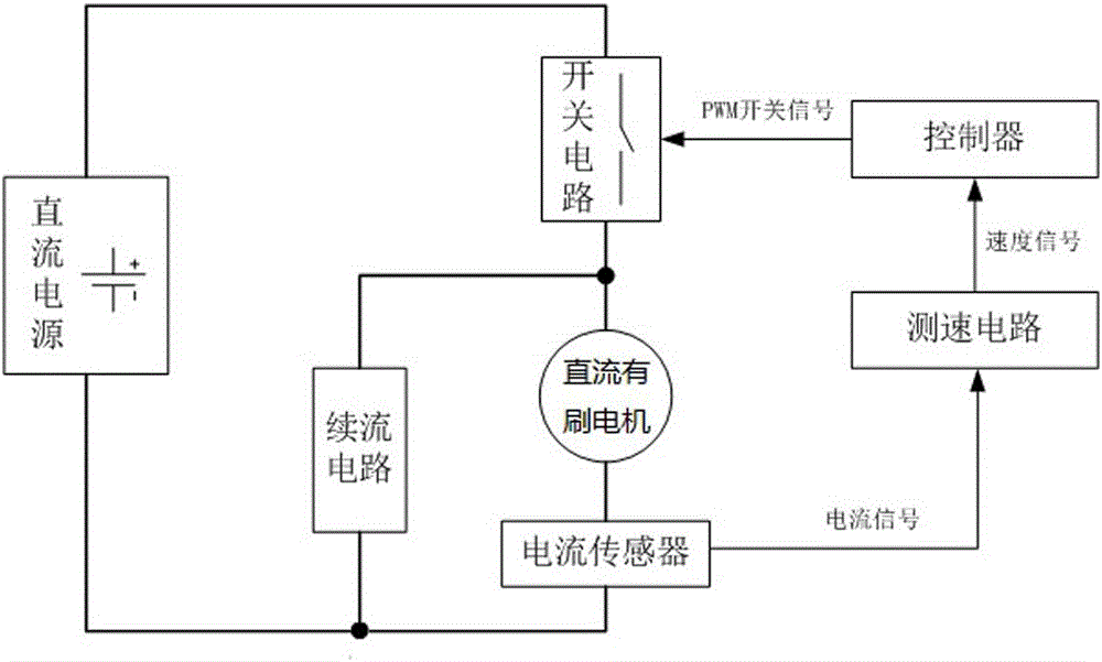
[0049] Such as figure 2 with image 3 As shown, the DC brushed motor speed control device of the present invention includes an adjustable power supply, and a DC brushed motor and a current sensor are sequentially connected in series between the positive terminal and the negative terminal of the adjustable power supply through wires. The current sensor is connected with a speed measuring circuit through a wire, the speed measuring circuit is connected with a controller through a wire, and the controller is connected with the adjustable power supply through a wire. The speed measurement circuit includes a filter amplifier circuit and a signal comparison circuit, the filter amplifier circuit and the signal comparison circuit are connected through wires, the filter amplifier circuit is connected with the current sensor through wires, and the signal comparison circuit is connected with the controller through wires. The controller has a built-in logical operation unit.

[0050] W...


PUM


Abstract

The invention relates to a speed regulation device and speed regulation method of a DC brush motor. The speed regulation device and the speed regulation method are characterized in that a current signal of the DC brush motor is acquired by a current sensor; the current signal is filtered and amplified by a filtering amplification circuit; the current signal is converted to a high-low alternating square wave speed signal by a single comparison circuit; the rotational speed of the motor is obtained through calculation by a controller according to the period or the frequency of the speed signal combined with the number of mica plates in a motor commutator; and finally, an instruction signal is sent to an adjustable power supply from the controller, and the purpose of adjusting the rotational speed of the motor is achieved by controlling the DC voltage amplitude of the motor. With the speed regulation device and the speed regulation method, the speed of the motor can be measured and adjusted by single circuit combination, an extra large-scaled device is not needed, and the speed regulation device and the speed regulation method are relatively low in cost; and moreover, no limitation is generated to an application environment and a mechanical structure of the motor, the speed measurement result is more accurate, and the rotational speed of the motor can be adjusted and controlled better.

Description

technical field [0001] The invention relates to a speed regulating device, in particular to a speed regulating device and method for the rotation of a commutator (ie, a rotor) of a DC brushed motor. Background technique [0002] DC brushed motors are widely used in industrial and civil industries. In order to realize the adjustment of the rotational speed of the brushed DC motor, it is necessary to detect the rotational speed of the motor first, and then control it. At present, the speed detection of brushed motors mainly uses methods such as tachogenerators, photoelectric encoders, and Hall sensors. These methods usually require additional equipment on the motor, which not only greatly increases the cost, but also affects the use. There are also higher requirements for the environment and the mechanical structure of the motor. Contents of the invention [0003] The problem to be solved by the present invention is to provide a DC brushed motor speed control device, which...

Claims


Application Information

Patent Timeline
IPC IPC(8): H02P7/06
CPCH02P7/06
Inventor 季欣杰孔小明戴政
Owner JIANGSU REYA ELECTRIC
Why Eureka
Try Eureka