A Process-Layer Optical Network Structure of Inter-Wavelength Multicast

A technology of network structure and process layer, which is applied in optical fiber transmission, wavelength division multiplexing system, electromagnetic wave transmission system, etc., can solve the problems of in-depth research and no technical means, and achieve the reduction of the number of optical fibers and the orderly and concise network structure , Improve the effect of data transmission rate

Active Publication Date: 2018-04-24
SOUTHEAST UNIV
View PDF5 Cites 0 Cited by
  • Summary
  • Abstract
  • Description
  • Claims
  • Application Information

AI Technical Summary

Problems solved by technology

However, the research on the key core issues restricting the application of relay protection network mining network hopping technology, that is, reliable sampling data synchronization technology and intra-station Ethernet communication reliability guarantee technology that meets the requirements of relay protection, is still not in-depth; In the application mode, the sampling data synchronization needs to rely on an external synchronization source, and for the reliable guarantee of the network transmission of the protection sampling trip data, at present, it mainly relies on reserving a larger network load margin, and there is no better technical means

Method used


Image

  • A Process-Layer Optical Network Structure of Inter-Wavelength Multicast
  • A Process-Layer Optical Network Structure of Inter-Wavelength Multicast
  • A Process-Layer Optical Network Structure of Inter-Wavelength Multicast

Examples


Embodiment Construction

[0035] The present invention will be further described below in conjunction with embodiment and accompanying drawing.

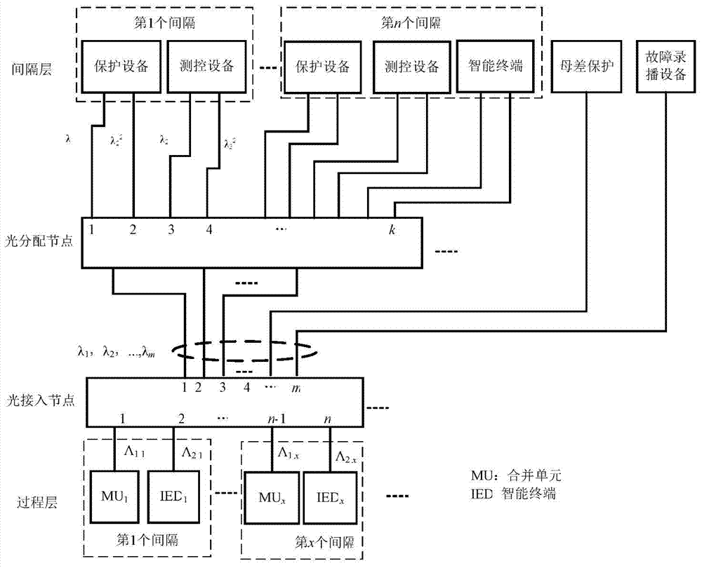
[0036] "Bay layer multicast device" refers to a device that needs to communicate with multiple given devices at the process layer at the same time, such as protection equipment, measurement and control equipment, protection measurement and control equipment, and intelligent terminals.

[0037] "Semi-full broadcast equipment at bay layer" refers to equipment that needs to receive uplink data from all or almost all devices at the process layer, such as bus differential protection equipment and fault recording and broadcasting equipment.

[0038] Such as figure 1Shown is an example of a specific structural scheme of the inter-wavelength multicast process layer optical network. The network consists of two intermediate optical nodes that interconnect the network devices at the process layer and the interval layer in groups. The optical nodes on the device side of ...


PUM


Abstract

The invention discloses a wave length mutual multicasting type process level optical network structure. The wave length mutual multicasting type process level optical network structure is characterized in that a plurality of groups of process level network devices are interconnected with a plurality of groups of bay level multicasting devices in a group-to-group correspondence manner through intermediate optical nodes, and all the process level network devices are connected with bay level semi-broadcasting or full-broadcasting devices; the intermediate optical nodes include optical access nodes and optical distribution nodes, wherein the optical access nodes are optical nodes on the process level side, and the optical distribution nodes are optical nodes on the bay level side; each group formed through the group-to-group correspondence interconnection includes at least two of the process level network devices and at least two of the bay level multicasting devices. The wave length mutual multicasting type process level optical network structure provided by the invention has the advantages that the required number of optical fibers is greatly reduced, the network structure is more orderly and simpler, the implementation is simple, and the maintenance is easy; through the wave length mutual multicasting of the intermediate optical nodes, the optical layer multicasting function and the sharing of network information on an optical layer are achieved, and the ''network sampling and network hopping'' method can be used; automatic network restructuring can be further achieved when optical cross connectors are adopted in the optical distribution nodes.

Description

technical field [0001] The invention belongs to the technical field of electric power system communication, relates to an electric power application optical communication network, and in particular relates to a process layer optical network system structure of an intelligent substation. Background technique [0002] The construction of smart grid is an important task for the development of power automation in my country. At present, the relay protection in substations mostly adopts direct mining and direct jumping to ensure reliable connection and communication QoS performance, but its wiring is complicated and maintenance is difficult, which will cause a lot of waste of cables or optical cables, and information cannot be shared. Networking with relay protection, that is, network mining and network jumping, can realize the sharing of network information, greatly simplify optical fiber wiring, improve debugging efficiency, and save construction costs. However, the research o...

Claims


Application Information

Patent Timeline
Patent Type & Authority Patents(China)
IPC IPC(8): H04B10/25H04B10/032H04J14/02H04Q11/00
CPCH04B10/032H04B10/2589H04J14/0204H04Q11/0067H04Q2011/0075H04Q2011/009
Inventor 樊鹤红胡威漪孙小菡朱敏
Owner SOUTHEAST UNIV
Why Eureka
Try Eureka