Push-button vessel wall mri with 3d scout scan

A technology of searching and scanning the vessel wall, applied in the direction of using nuclear magnetic resonance imaging system for measurement, using magnetic variable measurement, instruments, etc., can solve problems such as error-prone, and achieve the effect of reducing the duration

Active Publication Date: 2016-06-15
KONINKLJIJKE PHILIPS NV +1
View PDF3 Cites 0 Cited by
  • Summary
  • Abstract
  • Description
  • Claims
  • Application Information

AI Technical Summary

Problems solved by technology

Thus, successful completion of all scans requires e

Method used

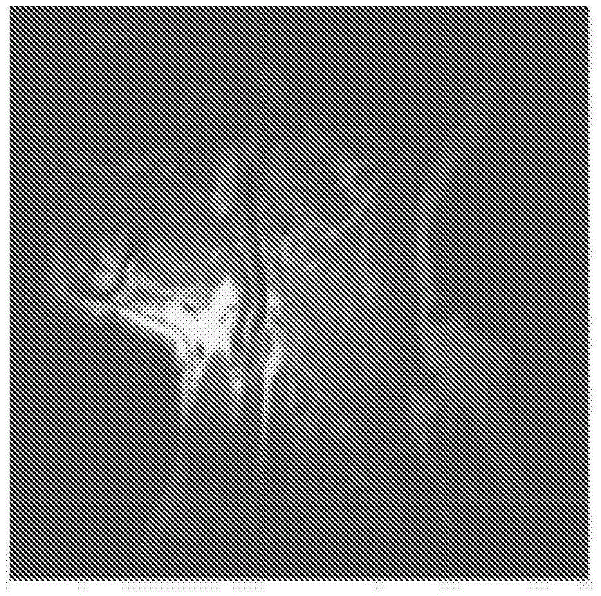
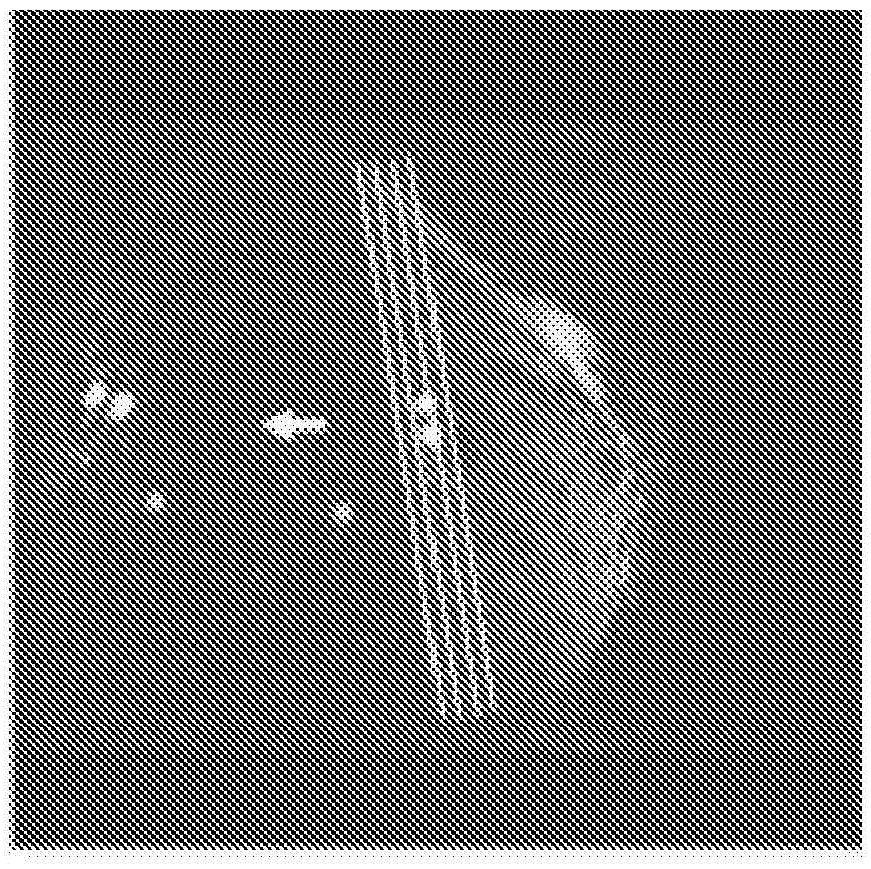
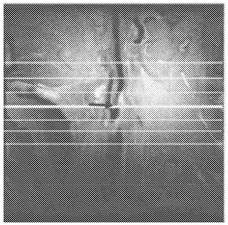

Image

  • Push-button vessel wall mri with 3d scout scan
  • Push-button vessel wall mri with 3d scout scan
  • Push-button vessel wall mri with 3d scout scan

Examples


Example Embodiment

[0024] Known approaches for magnetic resonance (MR)-based vascular wall imaging include complex workflows that typically require three to four locators and / or search scans before diagnostic scans can be performed. In addition, planning scans requires thorough training and can be prone to errors. This application uses advances in hardware and three-dimensional (3D) imaging to provide enhanced approaches for vascular wall imaging, including workflows that reduce the required human interaction. The workflow can include user interaction as little as a simple tap or push of a button (eg, "start" button).

[0025] reference figure 2 The imaging system 10 utilizes MR and enhanced approaches for vascular wall imaging to generate one or more diagnostic images of the target vessel (such as the carotid artery) of the patient 12. The system 10 includes a scanner 14 that defines an imaging (or scanning) volume 16 that is sized to fit the target vessel. The patient support can be used to sup...


PUM


Abstract

A medical system (10)and method(100)image a vessel wall automatically. A scout scan of a patient for localizing a target vessel of the patient is automatically performed (102) using magnetic resonance (MR). The scout scan is three-dimensional (3D) and isotropic. An MR data set of the scout scan is automatically reconstructed (104) into foot-to- head (FH), left-to-right (LR) and posterior-to-anterior (PA) projections. A3D imaging volume (16)encompassing the target vessel is automatically determined (106) from the projections, and a diagnostic scan of the 3D imaging volume (16) is performed (108) using MR.

Description

technical field [0001] The present application relates generally to magnetic resonance (MR) imaging. The present application finds particular application in connection with vessel wall imaging and will be described with particular reference to vessel wall imaging. However, it should be understood that the present application also applies to other use cases and is not necessarily limited to the applications described above. Background technique [0002] MR-based imaging of vessel walls, such as MR-based plaque imaging, has a number of advantages over vessel wall imaging based on other imaging modalities such as computed tomography (CT) and ultrasound (US). These advantages include better soft tissue contrast and more elastic image contrast. Despite these advantages, the clinical adoption of MR-based vessel wall imaging has been relatively slow. Among other things, MR-based vessel wall imaging is slow and has a complex workflow compared to vessel wall imaging based on other...

Claims


Application Information

Patent Timeline
IPC IPC(8): G01R33/54G01R33/563
CPCG01R33/543G01R33/5635A61B5/055G01R33/34G01R33/385G01R33/5602
Inventor 王津楠P·博尔纳特苑纯
Owner KONINKLJIJKE PHILIPS NV
Why Eureka
Try Eureka