
Transparent soil model test device for mining area pile foundation bearing force and test method

A model test device and transparent soil technology, which can be used in the test of foundation structure, foundation structure engineering, construction, etc., can solve the problems of not being able to simulate the deformation of the soil subsidence process in the mining area, and improve the efficiency of scientific research and test operation. convenient effect

Inactive Publication Date: 2016-06-22
HENAN POLYTECHNIC UNIV
View PDF6 Cites 40 Cited by
  • Summary
  • Abstract
  • Description
  • Claims
  • Application Information

AI Technical Summary

Problems solved by technology

[0006] The purpose of the present invention is to overcome the defects that the traditional pile foundation bearing capacity model test in the mining area cannot simulate the soil subsidence process in the mining area well and cannot directly observe the internal deformation of the soil around the pile, and proposes a pile foundation bearing capacity test in the mining area. Mechanical transparent soil model test device, which can realize various working conditions, including different pile types, different sizes, different buried depths, single piles and pile groups and other common working conditions in actual engineering; the model test uses PIV technology to observe transparent soil Internal displacement of the body, high precision; small size of the device, short test preparation time, convenient test operation, not only improves the efficiency of scientific research, but also can be used as a teaching instrument

Method used


Image

  • Transparent soil model test device for mining area pile foundation bearing force and test method
  • Transparent soil model test device for mining area pile foundation bearing force and test method
  • Transparent soil model test device for mining area pile foundation bearing force and test method

Examples


Embodiment Construction

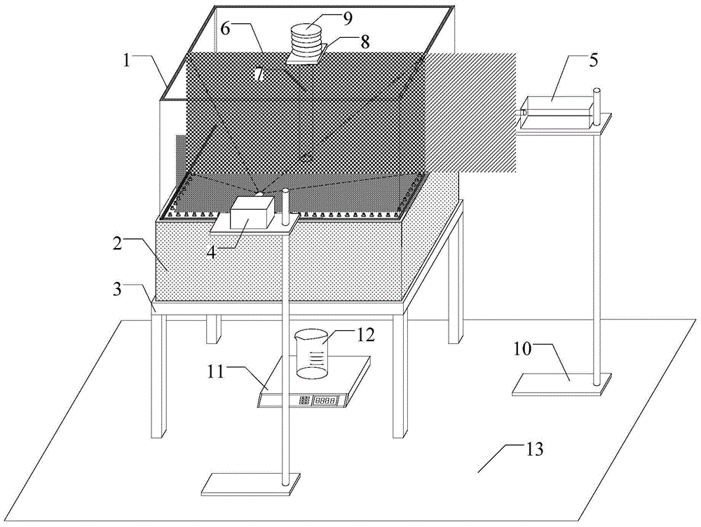
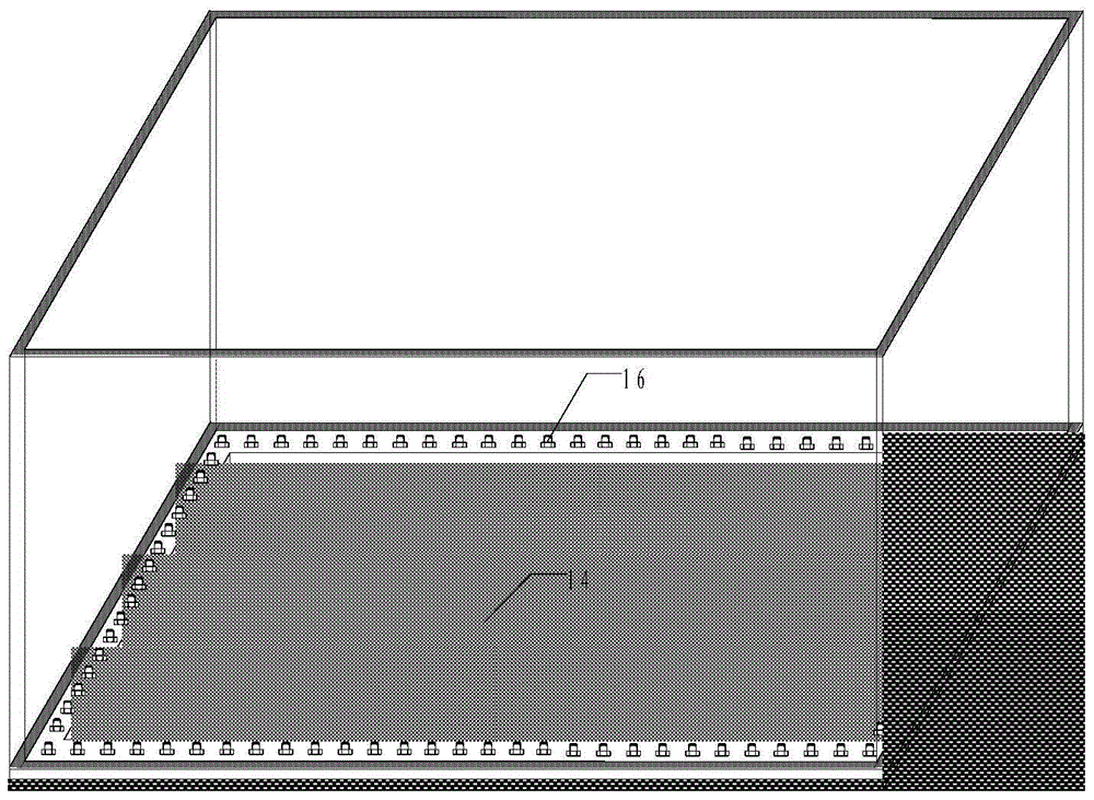
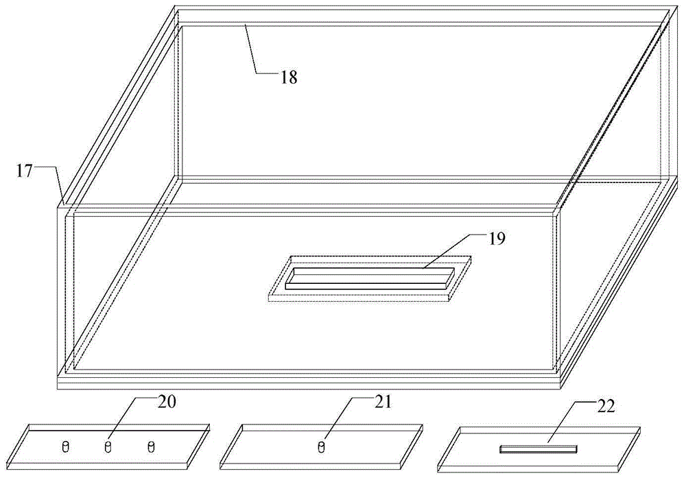
[0040] like Figure 1-4Shown, the mining area pile foundation bearing capacity transparent soil model test device structure of the present invention is: comprise base 3, plexiglass sand box 2, transparent soil model box 1, electronic scale 11, pile body 7, weight 9, high precision industrial camera 4 and linear laser generator 5; the plexiglass sand box 2 is placed on the base 3, and the bottom of the plexiglass sand box 2 is provided with an opening, and the flow rate of sand in the plexiglass sand box 2 is controlled by adjusting the aperture, The sand box inner wall 18 is slightly lower than the sand box outer wall 17; the electronic scale 11 is placed below the opening, and the electronic scale 11 is placed with a beaker 12, which is used to measure the weight of the sand flowing out and control the settlement; the transparent soil model box 1 is embedded on the sand box, and the bottom surface of the transparent soil model box 1 is a layer of latex film 14, which is used ...


PUM


Abstract

The invention discloses a transparent soil model test device for mining area pile foundation bearing force. The transparent soil model test device comprises a base, a sand box, a transparent soil model box, an electronic scale, a pile body, a loading device, a CCD industrial camera and a laser linear generator. The sand box is arranged on the base. An open hole is formed in the bottom of the sand box. The electronic scale is arranged below the open hole and used for measuring the weight of outflow sand. The transparent soil model box is embedded in the upper portion of the sand box. The bottom face of the transparent soil box is a layer of emulsion film and used for isolating transparent soil from sand soil. The pile body is arranged in the transparent soil. A pile cap is arranged at the pile top. The load is applied to the pile cap. The pile body is provided with marking points for monitoring displacement of the pile body. The laser linear generator is arranged on one side of the test device. By the adoption of the transparent soil model test device, mining subsidence caused by coal mining is simulated through a sand leakage method, so that the mining area earth surface soil mass subsidence process is simulated; and meanwhile, the method can be used for earth surface soil mass horizontal movement or vertical movement caused by similar human engineering activities by changing the sand leakage position and the pore size.

Description

technical field [0001] The invention relates to a transparent soil model test device and method for the bearing capacity of pile foundations in mining areas, which are mainly used in the technical field of research on bearing mechanics of pile foundations in mining areas. Background technique [0002] With the large-scale mining of coal, large-scale and large-scale mining areas have been formed in many areas. With the further development of coal resources, the area of ​​mining areas has continued to increase. "Three downs" (under water, under railways, under buildings) coal mining, especially coal mining under buildings, poses a serious threat to the stability and safety of buildings built above the mining area. The mining process often causes the surface soil to move horizontally, sink or even collapse. The horizontal displacement of the surface soil will cause additional internal force and deformation of the pile foundation of the adjacent building, and the subsidence of t...

Claims


Application Information

Patent Timeline
IPC IPC(8): E02D33/00
CPCE02D33/00
Inventor 张敏霞徐平崔文杰王兴国徐海宾闫芙蓉牛月君高帅
Owner HENAN POLYTECHNIC UNIV
Learn More