Turbine engine

A turbine engine and turbine technology, which is applied to engine components, machines/engines, gas turbine devices, etc., can solve the problems of unstable combustion of turbine engines, and achieve the effects of improving fuel economy and working reliability, improving thermal efficiency and simple structure.

Active Publication Date: 2018-04-10
清航空天(浙江)科技有限公司
View PDF5 Cites 0 Cited by
  • Summary
  • Abstract
  • Description
  • Claims
  • Application Information

AI Technical Summary

Problems solved by technology

[0004] Another object of the present invention is to provide a turbine engine, which solves the problem of unstable combustion of traditional turbine engines, improves the thermal efficiency of combustion, and improves the fuel economy and working reliability of the engine

Method used


Image

  • Turbine engine
  • Turbine engine
  • Turbine engine

Examples


Embodiment Construction

[0024] The turbine engine according to the present invention will be described in detail below with reference to the accompanying drawings.

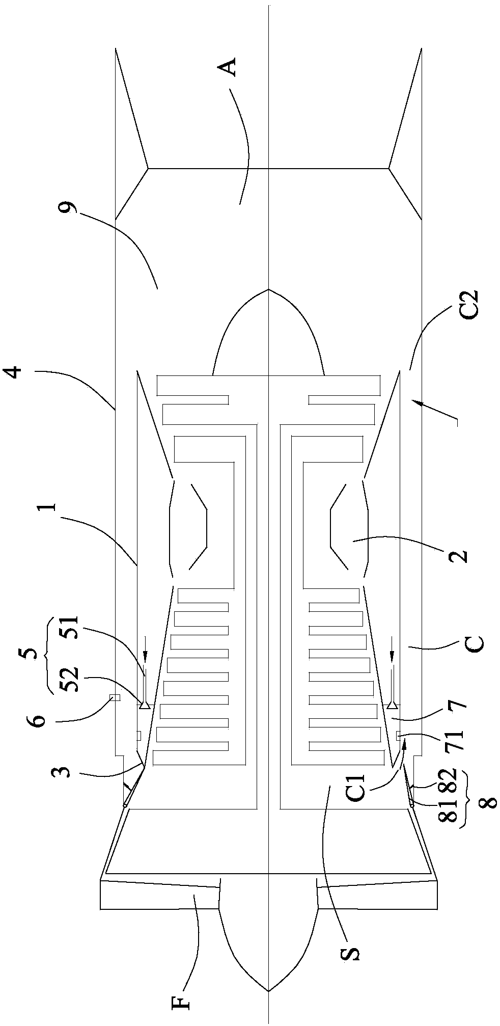
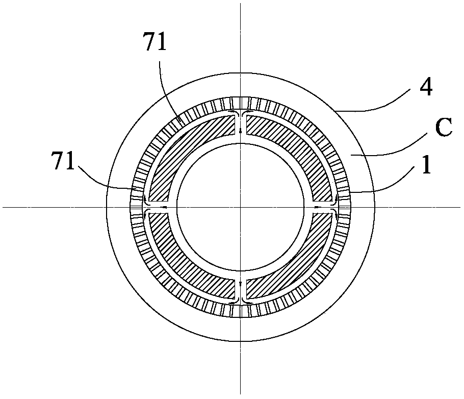
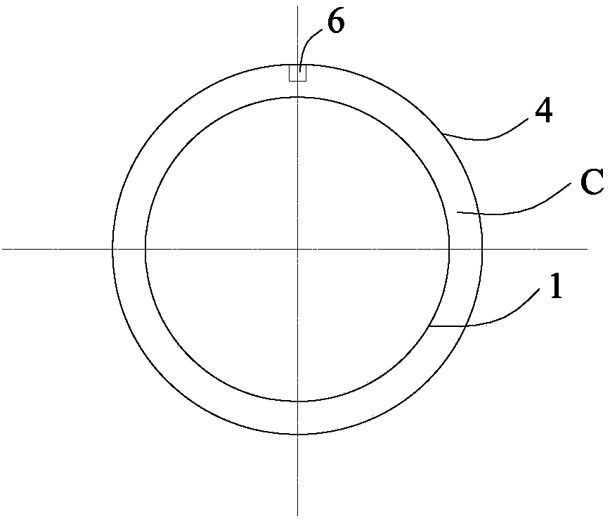
[0025] refer to Figure 1 to Figure 4 , The turbine engine according to the present invention includes: a casing 1 , a turbine 2 , a splitter ring 3 , a housing 4 , an oil circuit assembly 5 and an igniter 6 .

[0026] The turbine 2 is housed in the casing 1 . The shunt ring 3 is connected to the front end of the casing 1 and sleeved on the turbine 2 together with the casing 1 . The casing 4 accommodates the casing 1 and forms an external combustion chamber C with the outer wall of the casing 1 , while the splitter ring 3 and the inside of the casing 1 form an internal airflow channel S. The oil circuit assembly 5 is connected to the external combustion chamber C in a controlled manner, so as to provide fuel (ie, fuel oil) to the external combustion chamber C. The igniter 6 is arranged in the external combustion chamber C, and is used...


PUM


Abstract

The invention provides a turbine engine. The turbine engine comprises a receiver, a turbine, a shunt ring, a shell, an oil way component and an igniter. The shunt ring is connected to the front end of the receiver, and coats the turbine with the receiver. The shell accommodates the receiver, and forms an outer culvert combustion chamber with the outer wall surface of the receiver; and the shunt ring and the internal of the receiver form an inner culvert airflow channel. The oil way component is controlled to communicate to the outer culvert combustion chamber. The igniter is arranged in the outer culvert combustion chamber for igniting gas to generate knocking combustion of the gas. In the turbine engine, the outer culvert combustion chamber is simple in structure and light in weight, so that the thrust-weight ratio of the engine is largely increased. As the igniter is arranged in the outer culvert combustion chamber, the gas entering the outer culvert combustion chamber can rotate to generate the knocking combustion, the problem of unstable combustion of a traditional turbine engine is solved, the combustion heat efficiency is improved, and the fuel economy and the working reliability of the turbine engine are improved.

Description

technical field [0001] The invention relates to the technical field of aerodynamics, in particular to a turbine engine. Background technique [0002] At present, high thrust-to-weight ratio is still an important performance index pursued by aviation gas turbine engines. There are two main ways to increase thrust-to-weight ratio: one is to reduce weight; the other is to increase thrust. Regarding the first point, under the existing material and technological level conditions, in order to ensure the strength and life requirements, the space for weight reduction is very limited. For the second point, the main ways to achieve it are to increase the flow rate and increase the engine temperature rise level. Since the size of the inlet section is restricted by the aircraft, the flow rate cannot be increased arbitrarily. Therefore, in a short period of time, increasing the thrust can only be considered from the perspective of increasing the temperature rise ratio of the engine. Fo...

Claims


Application Information

Patent Timeline
Patent Type & Authority Patents(China)
IPC IPC(8): F02C3/14F02C7/04F02C7/264F02C7/22
CPCF02C3/14F02C7/04F02C7/22F02C7/264
Inventor 计自飞王兵谢峤峰张会强
Owner 清航空天(浙江)科技有限公司
Why Eureka
Try Eureka