Gas-liquid coupling turbine blade cooling unit

A technology of cooling unit and turbine blade, applied in the direction of blade support element, engine element, machine/engine, etc., can solve the problems of reducing the temperature of aero-engine turbine blades, thermal stress concentration of blades, and strengthening heat conduction, so as to improve the thrust-to-weight ratio. , the effect of increasing the liquid cooling path and increasing the heat exchange area

Active Publication Date: 2017-08-18
NANJING UNIV OF AERONAUTICS & ASTRONAUTICS
View PDF5 Cites 10 Cited by
  • Summary
  • Abstract
  • Description
  • Claims
  • Application Information

AI Technical Summary

Problems solved by technology

In 2003, Quan Dongliang and Yu Xinhua in the Journal of Northwestern Polytechnical University published an article "Numerical Simulation Research on the Influence of Flow-around Columns on the Flow Resistance Characteristics of Laminates", which showed that the use of turbulent columns will enhance the heat transfer of cold air in the laminates, but the turbulence The column will inevitably strengthen the conduction of heat in the laminate, which will cause the blade to heat up locally and cause the blade to have thermal stress concentration
[0004] However, there is no relevant research on the method of further reducing the temperature of the aeroengine turbine blades by adding a cold source pipe on the side of the spoiler column, and reducing the thermal stress concentration of the turbine blade due to the heat conduction of the spoiler column

Method used


Image

  • Gas-liquid coupling turbine blade cooling unit
  • Gas-liquid coupling turbine blade cooling unit
  • Gas-liquid coupling turbine blade cooling unit

Examples


Embodiment Construction

[0029] The principle and working process of the present invention will be further described below in conjunction with specific implementation and accompanying drawings.

[0030] like figure 1 As shown, the gas-liquid coupling turbine blade cooling unit disclosed in the present invention is a composite cooling structure of "impact / air film / turbulent flow" applied in a double shell type.

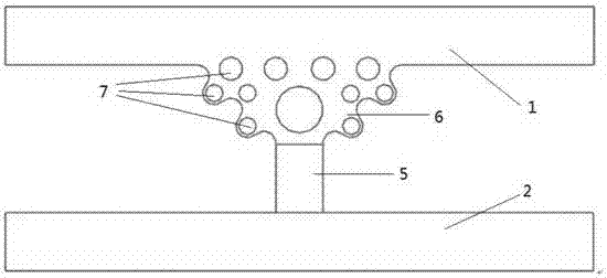
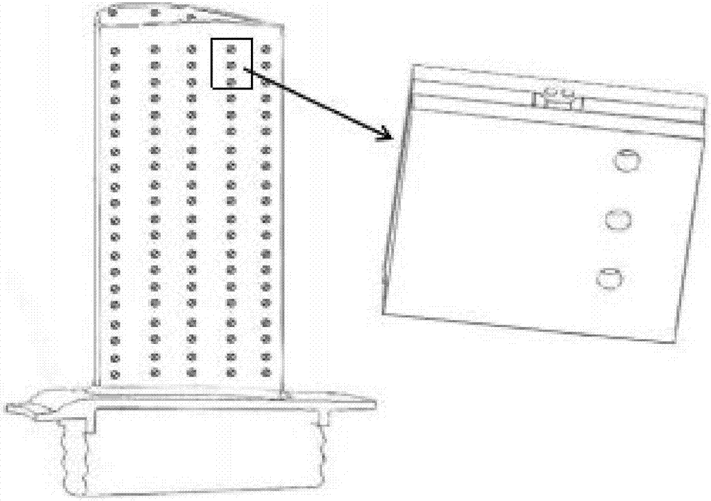
[0031] like Figure 2 to Figure 5 As shown, the gas-liquid coupling turbine blade cooling unit structure includes a cold air wall 1, a hot air wall 2, an impact hole 3, an air film hole 4, a spoiler column 5, a receiving platform 6, and a cold source pipeline 7 and other structures.

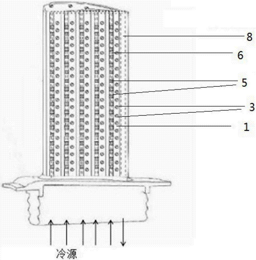
[0032] like image 3 As shown, the cooling unit in the embodiment has a cold air wall 1 , a hot air wall 2 , and a spoiler column 5 located between the cold air wall 1 and the hot air wall 2 . The cold air wall 1 is provided with multiple sets of impact holes 3 arranged in an array, wherein the multiple impact...


PUM


Abstract

Based on an existing double-layer shell type impact/gas film/turbulent flow composite cooling structure, the invention discloses a gas-liquid coupling turbine blade cooling unit. The gas-liquid coupling turbine blade cooling unit comprises a plurality of mutually independent cooling subunits. Each cooling subunit comprises a cold gas wall, a hot gas wall, a plurality of impact holes formed in the cold gas wall, a plurality of gas film holes formed in the hot gas wall, a plurality of turbulent flow columns located between the cold gas wall and the hot gas wall, and a collecting table connected with the cold gas wall and the turbulent flow columns, wherein the cold gas wall and the hot gas wall are arranged oppositely, the upper surface of the collecting table is connected with the inner surface of the cold gas wall, the lower surface of the collecting table is connected with the turbulent flow columns, and at least one cold source pipeline penetrating through the collecting table longitudinally is arranged in the collecting table. Further, in the cooling subunits, the side walls of the collecting tables are smoothly connected with the inner surfaces of the cold gas walls and the side walls of the turbulent flow columns to form a smooth hook face structure together. Through the gas-liquid coupling turbine blade cooling unit, a liquid cooling path is added, and the overall temperature of a turbine is further lowered.

Description

technical field [0001] The invention belongs to the technical field of engineering thermophysics, and in particular relates to a gas-liquid coupling turbine blade cooling unit. Background technique [0002] The early turbine blades of aero turbine engines did not adopt cooling technology, and the total temperature in front of the turbine was limited by the blade material, and it was difficult to exceed 1050 °C. As the performance of aero-engines, especially the thrust-to-weight ratio, gradually increases, the gas temperature at the turbine inlet becomes higher and higher. Fang Changde's "Aero-engine Development Research" published by Aviation Industry Press in 2009 mentioned that the temperature before the turbine will be as high as 2200-2300K, and at the same time the cooling technology is becoming more and more mature. [0003] At present, the impingement / air film or impingement / circumvention / air film composite cooling scheme is mainly used for the cooling of aero-engine ...

Claims


Application Information

Patent Timeline
Patent Type & Authority Applications(China)
IPC IPC(8): F01D5/18
CPCF01D5/186F01D5/187
Inventor 赵陈伟毛军逵淳杰王磊嵇润民
Owner NANJING UNIV OF AERONAUTICS & ASTRONAUTICS
Why Eureka
Try Eureka