Air inflation axial sealing device used in vacuum environment
A technology of axial sealing and vacuum environment, which is applied in the direction of engine sealing, measuring devices, aerodynamic tests, etc., can solve the problems of time-consuming and labor-intensive, reducing the service life of bellows, and the small adjustment distance of bellows, so as to reduce investment and The effect of operating cost, reducing labor intensity and improving replacement efficiency
- Summary
- Abstract
- Description
- Claims
- Application Information
AI Technical Summary
Problems solved by technology
Method used
Image

Examples
Embodiment 1
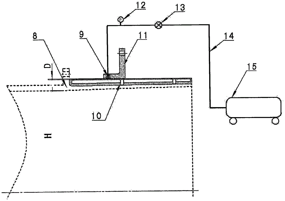
[0044] A gas-filled axial seal for vacuum environments, such as figure 2 As shown, it includes an inflatable sealing ring 9, a sealing cylinder 10, an adapter sleeve 11, a pressure gauge 12, a valve 13, an inflation pipeline 14 and an air compressor 15, wherein the inflating sealing ring 9, the sealing cylinder 10 and the adapter sleeve The cylinder 11 is an axisymmetric structure, which is illustrated in a two-dimensional cross-sectional view in the accompanying drawings;
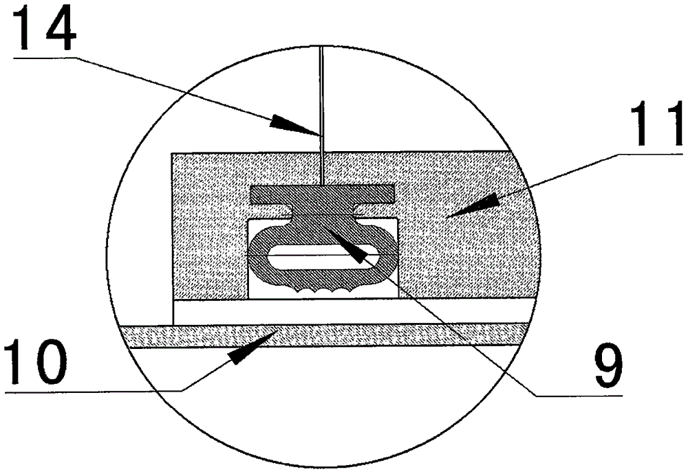
[0045] The inflatable sealing ring 9 is installed in the groove of the adapter sleeve 11, and it is guaranteed that the sealing ring 9 will not fall off at will when it is inflated or not inflated. It can be installed by means of glue, card slot, etc.; The interface is well matched with the inflatable interface of the adapter sleeve 11; the inflatable sealing ring 9 is not inflated during the whole installation process, see the attached image 3 ;
[0046] The adapter sleeve 11 is installed on the end (...
Embodiment 2
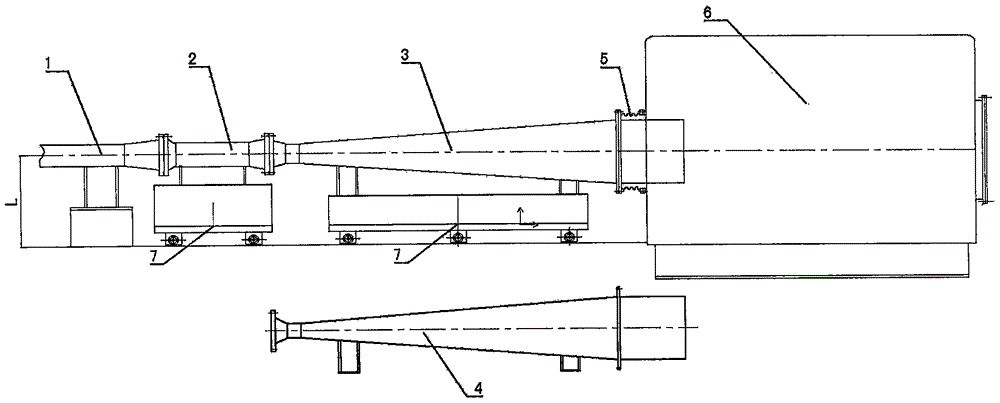
[0058] The inflatable axial sealing device of the present invention has been used in the Φ1 meter hypersonic wind tunnel of China Aerodynamic Research and Development Center, and is used for sealing between the nozzle and the test section. The outer diameter of the nozzle is about Φ1.1m, and it is a curved surface, so a straight sealing cylinder with an outer diameter of about Φ1.2m is processed and welded to the outer wall of the nozzle, and the inner diameter of the adapter sleeve is about Φ1.2m.
[0059] as attached Figure 6 (inflatable axial sealing device 17 is made of attached in the figure figure 2 The parts of the inflatable axial sealing device are connected), as shown in the figure, the operation steps of using the inflatable axial sealing device Φ1 meter hypersonic wind tunnel with different Mach number nozzles are as follows:
[0060] 1. Deflate the inflatable sealing ring 9 of the inflatable axial sealing device 17, the inflatable sealing ring 9 automatically r...
PUM
| Property | Measurement | Unit |
|---|---|---|
| Roughness | aaaaa | aaaaa |
Abstract
Description
Claims
Application Information
 - R&D
- Intellectual Property
- Life Sciences
- Materials
- Tech Scout
- Unparalleled Data Quality
- Higher Quality Content
- 60% Fewer Hallucinations
Browse by: Latest US Patents, China's latest patents, Technical Efficacy Thesaurus, Application Domain, Technology Topic, Popular Technical Reports.
© 2025 PatSnap. All rights reserved.Legal|Privacy policy|Modern Slavery Act Transparency Statement|Sitemap|About US| Contact US: help@patsnap.com