
Draining device for high-pressure heater regulating valve

A high-pressure heater and regulating valve technology, which is applied to steam traps, mechanical equipment, etc., can solve problems such as large impact on economy and safety, unsmooth drainage, and damage to regulating valves, and achieves simple structure and flow capacity. Strong and short maintenance period

Inactive Publication Date: 2016-06-22
CLP CHINA NUCLEAR POWER ENG TECH
View PDF0 Cites 0 Cited by
  • Summary
  • Abstract
  • Description
  • Claims
  • Application Information

AI Technical Summary

Problems solved by technology

This means that when the cage is draining water, the water flow through the through hole of the outer cage needs to go through the gap between the double-layer structure to reach the through hole of the inner cage; and due to the gap between the double-layer structure Smaller, it is easy to accumulate impurities, which will cause the problem of unsmooth drainage and even blockage
When blockage occurs, it is necessary to suspend the operation of the high-pressure heater and disassemble the cage of the control valve for cleaning, which has a great impact on the economy and safety of the unit, and the high frequency of cleaning will also affect the control valve cause damage

Method used


Image

  • Draining device for high-pressure heater regulating valve
  • Draining device for high-pressure heater regulating valve

Examples


Embodiment

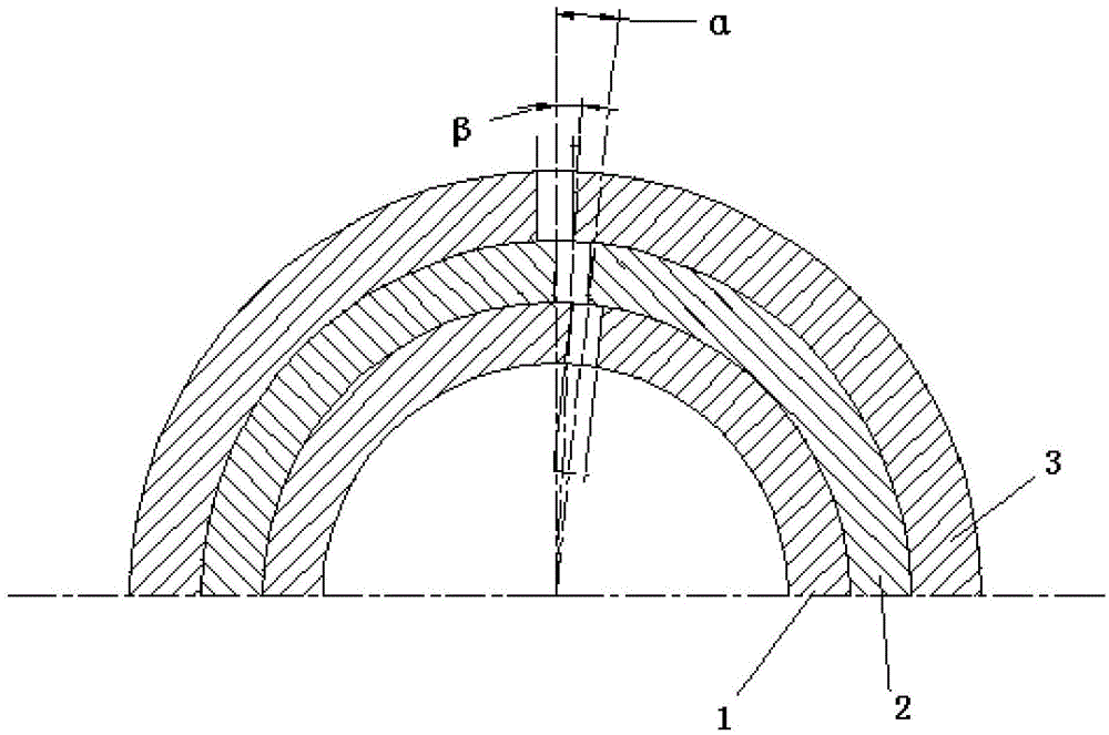
[0024] Such as figure 1 As shown in the figure, a drainage device for regulating valves of high-pressure heaters is composed of an inner cage 1, a middle cage 2 and an outer cage 3, and the middle cage 2 and the outer cage 3 are set in turn. Set on the inner valve cage 1. The multiple flow holes 4 on each layer of valve cages are divided into 4 repeating groups on average, and each repeating group corresponds to a 1 / 4 circle of the valve cage. There are 59 flow holes 4 in each repeating group, and the flow holes 4 It is divided into 12 columns at equal intervals, and the number is increased every 2 columns or every 3 columns. Wherein, the diameter of the flow hole 4 increases layer by layer from the inside to the outside.

[0025] In this embodiment, the hole diameter of the flow hole 4 of the inner cage 1 is 5 mm, the diameter of the flow hole 4 of the middle cage 2 is 5.5 mm, and the diameter of the flow hole 4 of the outer cage 3 is 6 mm. The center-to-center distance be...


PUM

PropertyMeasurementUnit
Pore diameteraaaaaaaaaa

Abstract

The invention relates to a draining device for a high-pressure heater regulating valve. The draining device comprises a plurality layers of valve cages which are combined by a layer-to layer sleeve manner; a plurality of through-flow holes are formed in each layer of valve cages; the through-flow holes in every two adjacent layers of valve cages under the same cross section are arranged in a half-hole staggering manner. Compared with the prior art, the draining device has the advantages that the structure is simple, the flow characteristic of the original valve can be remained, a valve element greatly avoids scouring, the draining performance is outstanding, blocking is difficultly caused, the flowing capacity is high, the dismounting and maintaining are convenient, and the maintenance period is short; and the cleaning frequency is effectively reduced, so that the use cost is decreased, and the safety and the reliability are ensured.

Description

technical field [0001] The invention relates to a draining device for a regulating valve, in particular to a draining device for a regulating valve of a high-pressure heater. Background technique [0002] High pressure heaters play a very important role in the production and operation of power plants. The high-pressure heater is a device located between the feedwater pump and the economizer or evaporator in the feedwater recuperation system of the power plant, which uses steam turbine extraction to heat the high-pressure feedwater. However, during the long-term operation of the high-pressure heater, the flow of the regulating valve is often poor or even blocked. After inspection, it was found that the cage of the original regulating valve was a double-layer structure, that is, it was composed of an inner cage and an outer cage. The connection is realized through the gap between the double-layer structure. This means that when the valve cage is draining water, the water fl...

Claims


Application Information

Patent Timeline
IPC IPC(8): F16T1/38
Inventor 冯文福杨成杨太勇林炯炯
Owner CLP CHINA NUCLEAR POWER ENG TECH
Learn More