Flow resistance test system of valve flow and method for performing little micro flow test by using the same

A technology for testing system and valve flow, applied in the testing of mechanical components, testing of machine/structural components, measuring devices, etc., to achieve the effect of improving measurement accuracy and precision

Active Publication Date: 2016-06-22
HEFEI GENERAL MACHINERY RES INST
View PDF5 Cites 18 Cited by
  • Summary
  • Abstract
  • Description
  • Claims
  • Application Information

AI Technical Summary

Problems solved by technology

Scientific and rational design of experimental devices is the prerequisite for accurate measurement of flow capacity and flow resistance coefficient, but under certain extreme conditions, such as large size and small opening, the existing technology has not yet provided accurate measurement technology for small and micro flow conditions

Method used


Image

  • Flow resistance test system of valve flow and method for performing little micro flow test by using the same
  • Flow resistance test system of valve flow and method for performing little micro flow test by using the same

Examples


Embodiment Construction

[0050] The technical solutions in the present invention will be clearly and completely described below in conjunction with the accompanying drawings in the embodiments of the present invention. Based on the embodiments of the present invention, all other embodiments obtained by persons of ordinary skill in the art without making creative efforts belong to the protection scope of the present invention.

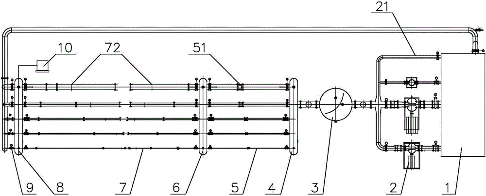
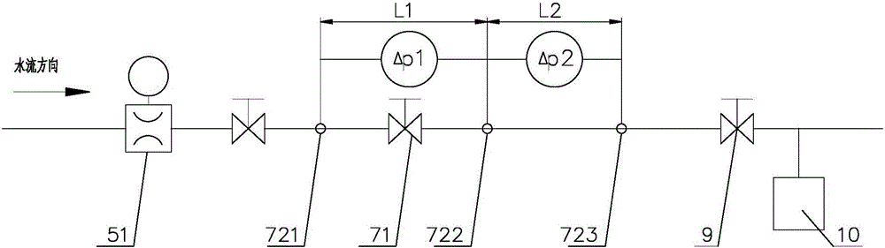
[0051] In the present invention, the tested valve 71 is in figure 1 not shown in the figure 1 The space between the middle pressure measuring points 72 is represented; and though not described in the text, the present invention is provided with a switch valve or a shut-off valve for the flow of the control medium in the flow measurement pipeline and the valve test pipeline.

[0052] A valve flow resistance test system

[0053] Such as figure 1 As shown, the system includes a water tank 1, a water pump 2, a pressure-stabilizing container 3, a water collector I4, a water separ...


PUM


Abstract

The present invention discloses a flow resistance test system of valve flow and a method for performing a little micro flow test by using the same. The system comprises a water tank, a water pump, a pressurizer, a water collector I, a water separator, a water collector II and a back pressure regulating valve which are connected in order through pipelines. The water collector I is connected with the water separator through a plurality of parallel flow measurement pipelines with different pipe diameters, and flowmeters with different apertures are respectively installed on the flow measurement pipelines; the water separator is connected with the water collector II through a plurality of parallel valve test pipelines with different pipe diameters, and valves with different apertures to be tested are respectively installed on the valve test pipelines; and the water collector II or the pipeline at the downstream of the water collector II is connected with a weighing device which is easy to accurately measure the little micro flow. According to the invention, the flow capability of the flow resistance test system of valve flow may be obtained by measuring the differential pressure through adoption of a Bernoulli equation; the flow resistance coefficient of the flow resistance test system of valve flow may be obtained according to measurement values such as flow velocity, differential pressure and the like; and moreover, the flow capability and the flow resistance coefficient of valves to be tested in various conditions may be accurately measured.

Description

technical field [0001] The invention belongs to the technical field of flow measurement, and in particular relates to a valve flow resistance test system and a small and micro flow measurement method. Background technique [0002] The valve is a fluid control component with a large quantity and a wide range, and is the most numerous resistance component in the process industry. The flow capacity and flow resistance coefficient of the valve are the main performances other than the strength and sealing performance of the valve, and they are also factors that must be considered when the process system design department selects a power device (such as a pump or compressor, etc.). The flow capacity and flow resistance coefficient of the valve are mainly measured by the test device. Scientific and rational design of experimental devices is the prerequisite for accurate measurement of flow capacity and flow resistance coefficient. However, under certain extreme conditions, such as...

Claims


Application Information

Patent Timeline
Patent Type & Authority Applications(China)
IPC IPC(8): G01M13/00
CPCG01M13/00
Inventor 张继伟王剑黄健黄明亚靳淑军彭林张绍华
Owner HEFEI GENERAL MACHINERY RES INST
Why Eureka
Try Eureka