

Suspension type UAV (unmanned aerial vehicle) water sampler system
A water quality sampler and unmanned aerial vehicle technology, applied in the direction of rotorcraft, aircraft, motor vehicles, etc., can solve the problems of change, easy blockage of sampling pipes, high cost, etc., and achieve the effect of simple operation, saving manpower, and convenient sampling
- Summary
- Abstract
- Description
- Claims
- Application Information
AI Technical Summary
Problems solved by technology
Method used
Image

Examples
Embodiment Construction
[0039] The present invention will be described in further detail below in conjunction with the accompanying drawings.
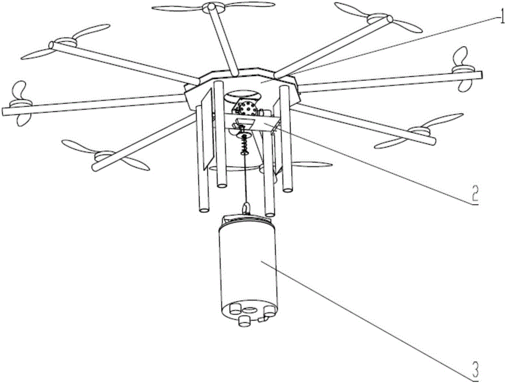
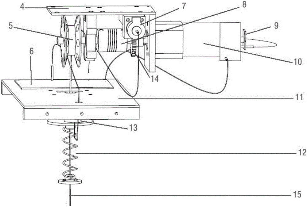
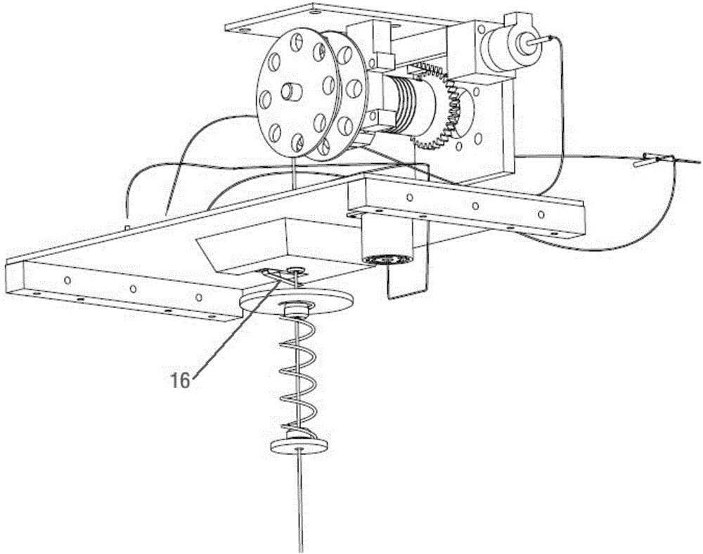
[0040] As shown in the drawings, the device consists of three parts: an unmanned aerial vehicle 1 , a sampling control system 2 and a sampling cup 3 . The sampling control system 2 is fixed to the bottom mounting plate of the unmanned aerial vehicle 1 through the motor fixing plate 4, fixed to the feet of the unmanned aerial vehicle 1 through the return baffle 11, and the sampling cup 3 is suspended on the winding shaft 5 through the sampling cup pull rope 15 superior. Wherein for the sampling control system 2, the bobbin 5, the self-locking motor 7, the shaft coupling 8, the rotational speed encoder 9, the sampling motor 10 and the self-locking gear 14 are fixed on the motor fixing plate 4, the central control board 6, the return buffer Device 12, water level probe 13, sampling cup stay cord 15 and return switch 16 are fixed on the return baffle plate 11. ...
PUM
 Abstract
Description
Claims
Application Information