Control circuit of electric tool

A technology for controlling circuits and power tools, which is used in motor control, electrical program control, DC motor speed/torque control, etc.

Active Publication Date: 2016-06-22
SKYBEST ELECTRIC APPLIANCE SUZHOU CO LTD
View PDF7 Cites 2 Cited by
  • Summary
  • Abstract
  • Description
  • Claims
  • Application Information

AI Technical Summary

Problems solved by technology

This will cause the output of the motor to be unstable. When the reciprocating

Method used


Image

  • Control circuit of electric tool
  • Control circuit of electric tool
  • Control circuit of electric tool

Examples


Embodiment Construction

[0019] The technical solution of the invention will be further described in detail below in conjunction with the accompanying drawings.

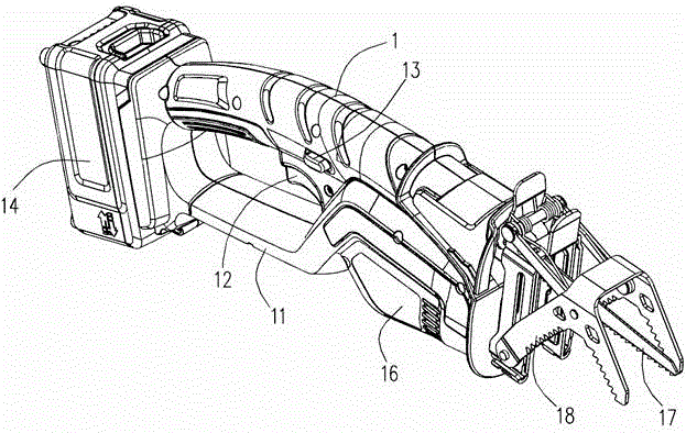
[0020] The present invention uses a reciprocating saw as the electric tool in the embodiment to illustrate the technical solution, but the technical solution of the present invention is not only used for the reciprocating saw, but also can be applied to other electric tools, such as pruners, hand-held pruners, etc. figure 1 The shown reciprocating saw includes a main body 1, on which is formed a handle part 11 that can be held by the operator, and a trigger switch 12 and a safety lock 13 are arranged at the lower part of the handle part, and the user presses the trigger switch 12 and the safety lock 13 at the same time when using to start. A battery pack 14 is arranged at the tail of the reciprocating saw, and the battery pack 14 can be separated from the tail of the reciprocating saw. A drive motor 16 is set at the front of the reciprocatin...


PUM


Abstract

The invention relates to a control circuit of an electric tool, which comprises a central control module, a motor drive module, a motor and a working parameter detection module. The working parameter detection module is electrically connected with the motor and the central control module. The working parameter detection module returns parameters detected during the operation of the motor to the central control module. The motor drive module is electrically connected with the motor by means of a first switch module and a second switch module respectively. The motor drive module controls intermittent on/off of the first switch module and the second switch module. The on/off state of the first switch module and the on/off state of the second switch module are always opposite. That is to say, when the first switch module is switched on, the second switch module is switched off; and when the first switch module is switched off, the second switch module is switched on. By means of the control circuit, the inductive impedance of the motor is well reduced, the speed of the motor is smoother, the influence of the load on the speed of the motor is smaller, and the run-out phenomenon of an electric chain saw is greatly reduced.

Description

technical field [0001] The invention relates to a control circuit of an electric tool, in particular to a control circuit of an electric reciprocating saw. Background technique [0002] During the use of some electric tools, it is often required that the motor of the electric tool can output stably, especially in electric tools that require high power output, it is particularly important to maintain a relatively stable speed of the electric tool motor. For example, in order to obtain a better cutting effect, the speed of the motor needs to be kept relatively stable when the reciprocating saw is started. If the motor speeds up and down during the rotation process, it is easy to cause the reciprocating saw to jump. Usually, the reciprocating saw uses silicon controlled rectifiers to realize the on and off of the motor power supply, and the speed of the motor is controlled by adjusting the ratio of the on and off time, that is, the speed of the motor is adjusted through the dut...

Claims


Application Information

Patent Timeline
IPC IPC(8): G05B19/18
CPCH02P7/28H02P29/02H02P3/12H02P29/032B23D51/16H02P7/285
Inventor 吴福飞
Owner SKYBEST ELECTRIC APPLIANCE SUZHOU CO LTD
Why Eureka
Try Eureka