Degassing device used before high pressure hydrolysis of glycerol stearate

A technology of glyceryl stearate and degassing device, which is applied in the directions of liquid degassing, auxiliary substance liquid degassing, chemical instruments and methods, etc., can solve the problems of uneven heating, difficult discharge of heat release, time-consuming and labor-intensive, etc. Achieve the effect of saving power resources, improving degassing efficiency and good degassing effect

Inactive Publication Date: 2016-06-29
NANYANG NORMAL UNIV
View PDF7 Cites 0 Cited by
  • Summary
  • Abstract
  • Description
  • Claims
  • Application Information

AI Technical Summary

Problems solved by technology

① and ② are not only expensive, but also have the problem of uneven heating or difficult discharge of exothermic heat, which is also one of the main reasons for the amplification effect in chemical production; in addition, chemical reactions often require stirring, which faces the problem of shaft sealing. Especially for high-pressure, high-temperature reactions and reactions that require high-speed stirring, it is more difficult or even impossible to solve the problem of shaft sealing.
③Although it can overcome the above shortcomings of ① and ②, it does not have a good ability to mix the reactants, so it needs to be equipped with a reactant stirring and mixing device
However, the raw material glyceryl stearate is vacuum degassed before hydrolysis, and the low boiling point substances in it will quickly pollute the vacuum pump oil and reduce the ultimate vacuum of the vacuum pump.
Replacing the vacuum pump oil not only increases the production cost, but also takes time and labor

Method used


Image

  • Degassing device used before high pressure hydrolysis of glycerol stearate
  • Degassing device used before high pressure hydrolysis of glycerol stearate

Examples


Embodiment Construction

[0017] In order to make the content of the present invention more obvious and understandable, the present invention will be described in detail below in conjunction with specific examples.

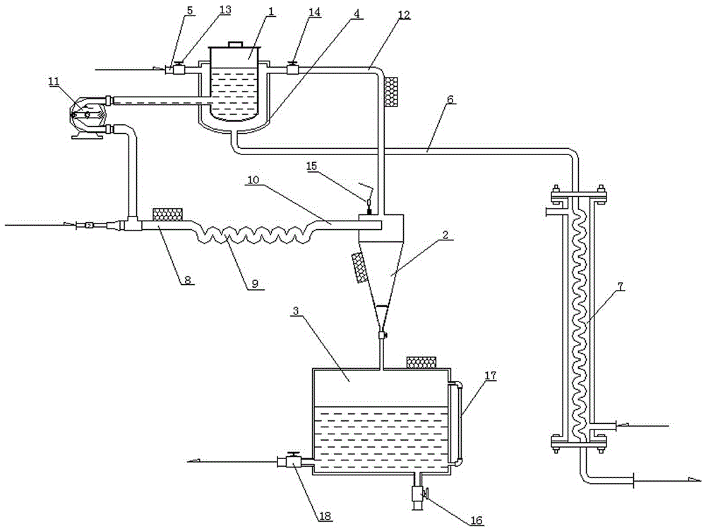
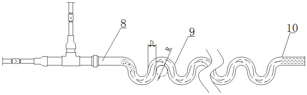
[0018] As shown in the figure, the degassing device before the high-pressure hydrolysis of glyceryl stearate includes a raw material oil tank 1, a reactor, a cyclone separation tank 2 and a degassed oil storage tank 3, and the outer casing of the raw material oil tank 1 is provided with a heating jacket 4, the top of the heating jacket 4 is provided with a water vapor inlet pipe 5, the water vapor inlet pipe 5 is provided with a steam valve 13, and the bottom of the heating jacket 4 is provided with a drain pipe 6; The feed pipe 8, the reaction pipe 9 and the discharge pipe 10 are composed of the feed pipe 8, the inlet end of the feed pipe 8 is connected with a three-way, and one of the feed ports of the three-way is connected to the raw material oil tank 1 through the hose pump 11, and the...


PUM


Abstract

The invention discloses a degassing device used before high pressure hydrolysis of glycerol stearate. The degassing device comprises a raw oil tank, a reactor, a cyclone separation tank and a degassed oil storage tank, wherein a heating jacket sleeves the raw oil tank, a water vapor inlet pipe is arranged at the top of the heating jacket, a drain pipe is arranged at the bottom of the heating jacket, the reactor is composed of a feeding pipe, a reaction pipe and a discharging pipe connected with one another in sequence, the inlet end of the feeding pipe is connected to a tee joint, one feeding hole of the tee joint is communicated with the raw oil tank via a hose pump, another feeding hole of the tee joint is connected to a water vapor generator, the reaction pipe is provided with a wavy pipe body, the discharging pipe of the reactor is communicated with the top of the cyclone separation tank, the bottom of the cyclone separation tank is communicated with the degassed oil storage tank, and the top of the cyclone separation tank is communicated with the heating jacket via a recovery pipe. The degassing device effectively enables water vapor and raw oil to be mixed uniformly so as to ensure a good degassing effect of the raw oil, can work continuously for a long period, and is low in running cost.

Description

technical field [0001] The invention belongs to the field of chemical production equipment, in particular to a degassing device before high-pressure hydrolysis of glyceryl stearate. Background technique [0002] The current chemical reaction equipment can be roughly divided into three categories: ①Reaction kettle (tank, tank); ②Reaction (absorption) tower; ③Reaction tube. ①, ② Not only the cost is high, but also the problem of uneven heating or heat release is not easy to discharge, which is also one of the main reasons for the amplification effect in chemical production; in addition, chemical reactions often need to be stirred, which faces the problem of shaft sealing. Especially for high-pressure, high-temperature reactions and reactions that require high-speed stirring, it is more difficult or even impossible to solve the shaft sealing problem. ③Although it can overcome the above-mentioned shortcomings of ① and ②, it does not have a good ability to mix the reactants, so ...

Claims


Application Information

Patent Timeline
Patent Type & Authority Applications(China)
IPC IPC(8): B01D19/00
CPCB01D19/001
Inventor 王利亚王玉芳汪彩露王孟娟李森兰
Owner NANYANG NORMAL UNIV
Why Eureka
Try Eureka