Rotating injection type oil mixing device

A rotary jetting and oil mixing technology, applied in mixers, packaging, mixers and other directions with rotary stirring devices, can solve the problems of inconsistent oil technical quality indicators, limited power of the storage tank drive system, complicated design and installation processes, etc. , to achieve the effect of simple design and installation scheme, simple structure and uniform quality

Inactive Publication Date: 2016-06-29
QINZHOU UNIV
View PDF6 Cites 10 Cited by
  • Summary
  • Abstract
  • Description
  • Claims
  • Application Information

AI Technical Summary

Problems solved by technology

The oil storage device is equipped with discharge and discharge pipes so that the oil is in a dynamic flow to achieve mixing, which is low in cost and has no potential safety hazards, but there are still the following defects: First, the power of the drive system of the storage tank is limited, and it can only be stirred and discharged. For oil products at the same level of the branch pipe and discharge branch pipe, the oil product in the tank can only undergo a small degree of laminar flow diffusion, resulting in low mixing uniformity of the oil product, so that the technical quality indicators of the upper, middle and lower oil products in the tank are inconsistent. In addition, Multiple branch pipes are installed, and the design and installation process is relatively complicated; secondly, the storage tank is not equipped with a stirring device, but the physical mixing of oil products is realized through the dynamic flow of downward suction and upper discharge countercurrent, and the single oil mixing method leads to uneven mixing , and the mixing efficiency is low

Method used


Image

  • Rotating injection type oil mixing device
  • Rotating injection type oil mixing device
  • Rotating injection type oil mixing device

Examples


Embodiment Construction

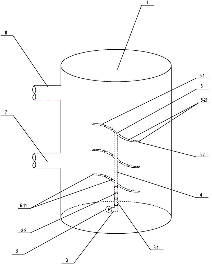
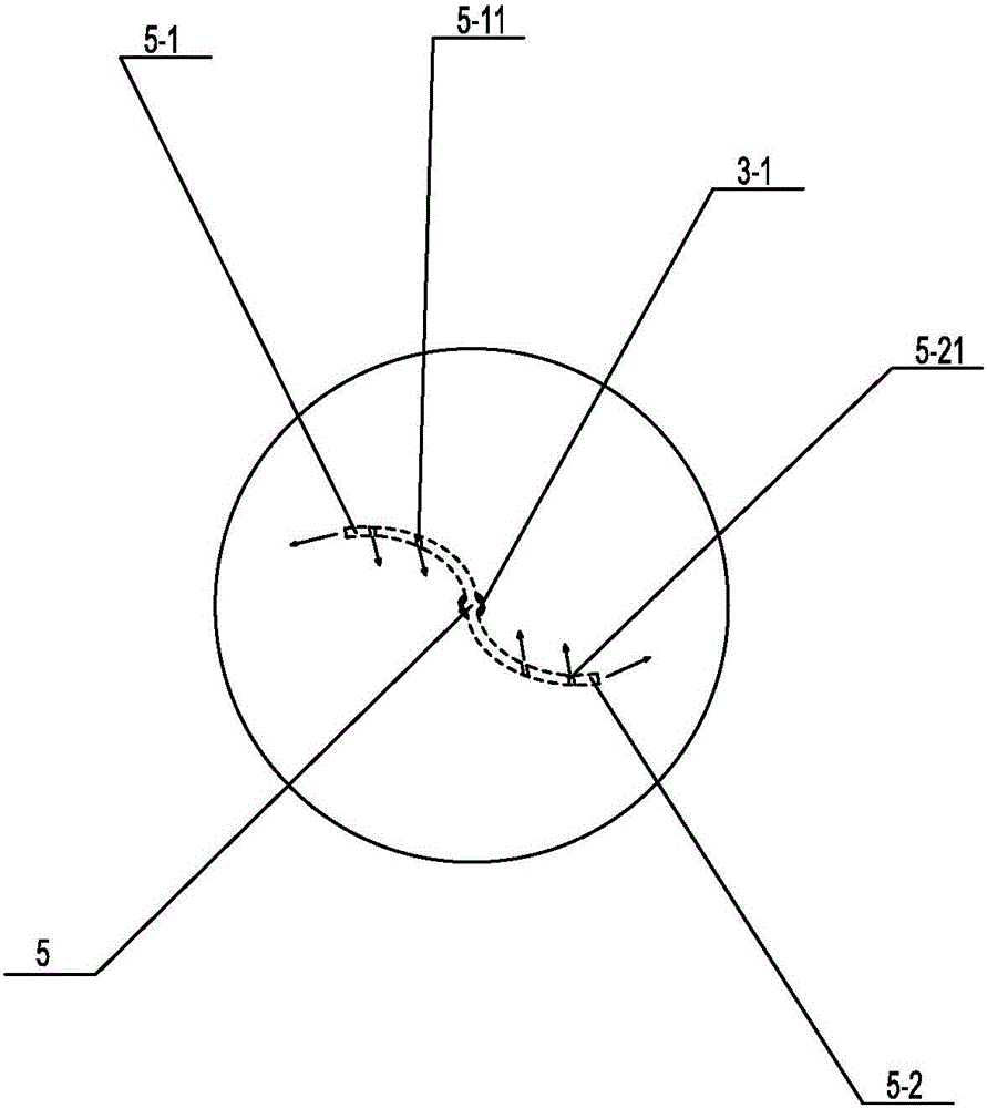
[0023] Such as figure 1 with figure 2 A specific embodiment of the present invention is proposed as shown, a rotary jet oil mixing device, comprising a tank body 1, the upper end of the tank body 1 outer wall is provided with an oil inlet pipe 6, and the lower end is provided with an oil outlet pipe 7, and the tank body 1 An explosion-proof servo-type submersible pump 2 is provided at the bottom of the inner chamber. The submersible pump 2 is connected to an external power supply through an explosion-proof power cord, and the output power is adjusted through frequency conversion. The submersible pump 2 is connected to a Vertically arranged delivery pipe 4, the rotatable part 3 includes a hollow bearing connector 3-1 connected to the submersible pump, a bearing 3-2 arranged in the bearing connector 3-1, and the bearing connector 3 -1 is set to be sealed and resistant to high-pressure erosion, effectively ensuring that the oil product reaches the delivery pipe 4 without leaka...


PUM


Abstract

The invention discloses a rotating injection type oil mixing device. The oil mixing device comprises a tank body, wherein an explosion-proof servo type immersed pump is arranged at the bottom inside the tank body and connected with a vertical delivery pipe through a rotatable component, a plurality of horizontally-mounted arc-shaped injection pipes are arranged on the delivery pipe in the vertical direction, the injection pipes comprise left injection branch pipes and right injection branch pipes which are symmetrically mounted with the delivery pipe serving as the center, and left injection holes and right injection holes capable of perpendicularly injecting an oil product to the inner wall of the tank body are symmetrically formed in the left injection branch pipes and the right injection branch pipes and are opposite in forming direction. The oil mixing device is simple in structure, convenient in design and mounting technology and easy to manufacture, the ejection effect is combined with mechanical stirring, and diversified oil mixing manners exist, so that the oil product in the tank body performs multidirectional composite motion including surging, rolling, agitating and the like, the oil product is high in mixing uniformity, the quality of the oil product in the tank body is uniform, and the oil mixing device further has the advantages of abrasion and impact resistance, high safety performance and the like and is worthy of wide popularization.

Description

technical field [0001] The invention relates to an oil storage device, in particular to a rotary jet oil mixing device. Background technique [0002] As we all know, blended refined oil or crude oil before refining is a multi-component mixture, usually placed in such image 3 Store in the oil storage tank shown. During the storage of oil products, due to the different densities of the components in the oil products, the oil storage tank is prone to stratification, that is, the quality of the upper, middle and lower oil products is inconsistent, which affects the subsequent processes. At present, in order to achieve the required oil quality, the commonly used methods and their disadvantages are as follows: first, through oil compounding, but this method is complicated and costly; second, through mechanical impeller blades for stirring, but its structure Complicated, the mixing uniformity is not high, and there are certain safety hazards; third, although the fixed or dynamic ...

Claims


Application Information

Patent Timeline
Patent Type & Authority Applications(China)
IPC IPC(8): B01F13/10B01F3/08B01F5/02B01F7/00B65D90/02
CPCB65D90/02B01F23/431B01F23/40B01F23/451B01F2025/912B01F25/27B01F27/11251B01F27/2123B01F33/822B01F2101/40
Inventor 梁金禄田根林樊栓狮石海信蒋有春李玉星李岩方丽萍钟莹莹周雄刘柑
Owner QINZHOU UNIV
Why Eureka
Try Eureka