Method for controlling temperatures of catalysts

A temperature control method and temperature controller technology, applied in chemical instruments and methods, chemical/physical processes, etc., can solve problems such as inability to adapt to requirements, and achieve the effects of reduced carrying capacity, simple equipment structure, and ease of use

Active Publication Date: 2016-06-29
石宝珍
View PDF4 Cites 0 Cited by
  • Summary
  • Abstract
  • Description
  • Claims
  • Application Information

AI Technical Summary

Problems solved by technology

[0005] In addition, the existing technology uses an external heat collector to cool the catalyst, and the catalyst entering the reactor is cooled under the

Method used


Image

  • Method for controlling temperatures of catalysts
  • Method for controlling temperatures of catalysts
  • Method for controlling temperatures of catalysts

Examples


Example Embodiment

[0038] Examples:

[0039] The catalyst entering temperature is 680℃;

[0040] The catalyst intake is 500T / h;

[0041] The catalyst outflow rate in the outer heat exchange zone is 300T / h;

[0042] The catalyst outflow rate in the inner heat exchange zone is 200T / h;

[0043] The temperature of the catalyst flowing out of the inner heat exchange zone is 600°C; the temperature of the catalyst flowing out of the outer heat exchange zone is 540°C;

[0044] Use water as cooling medium to produce 3.5MPa saturated steam; inlet water temperature is 190℃; water flow rate is 600T / h;

[0045] Use air as the fluidizing medium; the amount of fluidizing medium in the outer heat exchange zone: 2000Nm3 / h, and the amount of fluidizing medium in the inner heat exchange zone 1600Nm3 / h;

[0046] The fluidization medium flows out from the catalyst inlet;

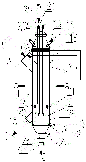
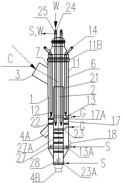
[0047] The inner diameter of the temperature controller housing 11 is 2200mm; the catalyst inlet is 1400mm; the inner diameter of the housing 21 of the inner h...


PUM


Abstract

The invention discloses a method for controlling the temperatures of catalysts. The method is characterized in that a common catalyst and fluidized medium mixing area is arranged at the upper part, and a heat exchange area is arranged under the mixing area; the heat exchange area is divided into two independent heat exchange units by an inner shell; each unit is internally and respectively provided with a heat exchange pipe, a fluidized medium distributor and a catalyst outlet; the catalyst from an inlet pipe enters the mixing area firstly and then enters two heat exchange units respectively, all the heat exchange units form a fluidized-bed condition under the action of fluidized medium, and the heat exchange amount of all the areas can be adjusted by changing the fluidized state, so that the temperatures of the catalysts flowing out of all the areas can be independently controlled.

Description

technical field [0001] The invention relates to a catalyst temperature control method, which is suitable for controlling the temperature of a catalyst entering a gas-solid reactor so that the catalyst meets the conditions required for the reaction, and is especially suitable for controlling the temperature of a catalytic cracking reaction cyclically regenerated catalyst. Background technique [0002] In the traditional catalytic cracking reaction process, the regenerant directly enters the reactor, but due to the need for coking, the regeneration temperature is often high. The temperature of the regenerant determines the catalyst-oil ratio of the reaction, which is crucial to the product distribution. High temperature reaction process also leads to undesired thermal cracking reaction, high regenerant temperature is unfavorable to the reaction; different positions of the reactor often require catalysts at different temperatures to achieve temperature control of the regenerated...

Claims


Application Information

Patent Timeline
IPC IPC(8): B01J8/24
CPCB01J8/1809B01J8/1836B01J8/1881B01J8/24B01J2208/00132
Inventor 石宝珍
Owner 石宝珍
Why Eureka
Try Eureka