Numerically controlled bus punching shearer

A punching and shearing machine and busbar technology, used in metal processing equipment, feeding devices, forming tools, etc., can solve problems such as prolonging clamping and positioning time, unable to process normally, reducing production efficiency, etc., to avoid damage to production time, The effect of improving processing efficiency and high processing efficiency

Inactive Publication Date: 2016-06-29
SHANDONG SHANHE CNC EQUIP CO LTD
View PDF9 Cites 8 Cited by
  • Summary
  • Abstract
  • Description
  • Claims
  • Application Information

AI Technical Summary

Problems solved by technology

It can be seen that in the prior art, the active X-axis movement of the main clamp and the passive X-axis movement of the auxiliary clamp have become a common design in the technical field of busbar punching and shearing machines. Actively moving driving components simplify the machine structure and save costs. The disadvantage is that after the main clamp clamps the bus bar, in order to complete the initial posi

Method used


Image

  • Numerically controlled bus punching shearer
  • Numerically controlled bus punching shearer
  • Numerically controlled bus punching shearer

Examples


Embodiment Construction

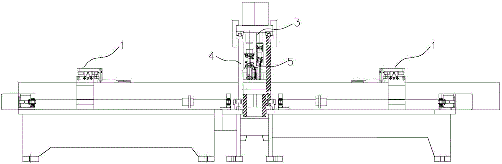
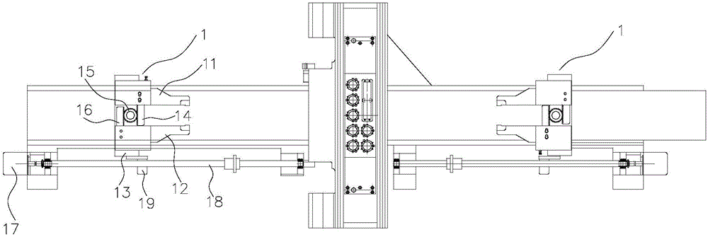
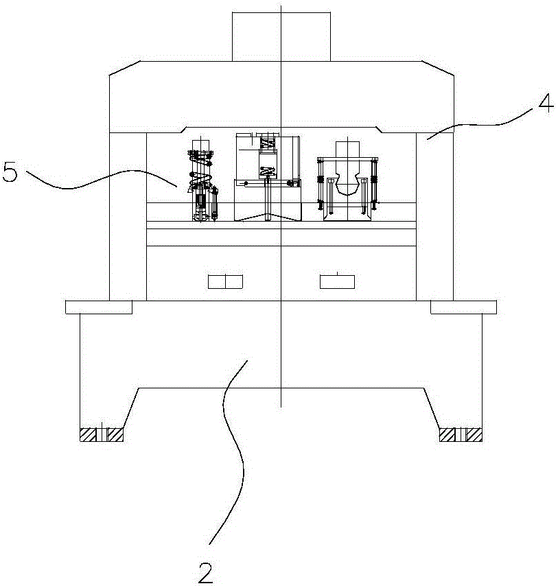
[0012] The specific implementation manners of the present invention will be described below in conjunction with the accompanying drawings. The invention discloses a numerically controlled busbar punching and shearing machine. The punching and shearing machine includes a frame 2 on which a feeding part and a striking assembly part 3 are arranged. The feeding part includes a clamp assembly, and the clamp assembly includes The main clamp assembly Ⅰ and the main clamp assembly Ⅱ, the main clamp assembly Ⅰ and the main clamp assembly Ⅱ are respectively located on both sides of the striking assembly part 3, the main clamp assembly Ⅰ and the main clamp assembly II all include: clamp base 13, clamp base 13 fits on the X-direction moving guide rail of frame 2; jaw, jaw includes active jaw 11 and passive jaw 12; active jaw opening and closing parts; clamp base The X-axis movement driving part is connected to the forceps base 13 .

[0013] In this embodiment, the X-axis movement driving...


PUM


Abstract

A numerically controlled bus punching shearer comprises a rack, wherein a feeding assembly part and a striking assembly part are arranged on the rack; the feeding assembly part comprises a gripper assembly; the gripper assembly comprises a main gripper assembly I and a main gripper assembly II; the main gripper assembly I and the main gripper assembly II are respectively positioned on two sides of the striking assembly part; each of the main gripper assembly I and the main gripper assembly II comprises a gripper seat, a jaw, an active jaw opening and closing driving component and a gripper seat X-axis moving driving component; each gripper seat is arranged on an X-axis moving guide track of the rack in a matched manner; each jaw comprises an active jaw and a passive jaw; and each gripper seat X-axis moving driving component is connected to the corresponding gripper seat. The traditional gripper design philosophy in the design of the bus punching shearer is changed, and technical prejudice is overcome. The numerically controlled bus punching shearer has the advantages of high machining efficiency (which can be three times that of the traditional bus processing machinery), and high workpiece positioning and machining precision.

Description

technical field [0001] The invention relates to the technical field of busbar (busbar) processing, in particular to a numerically controlled busbar punching and shearing machine with double active clamps. Background technique [0002] Busbars (including busbars) refer to products made of high-conductivity copper and aluminum row materials to transmit electric energy and have the ability to collect and distribute electric power. The busbar numerical control punching and shearing machine is a numerically controlled busbar punching and shearing machine specially processing the above-mentioned copper bar or aluminum bar. [0003] In the prior art, the clamps used to clamp the copper bar or aluminum bar to be processed on the bus bar numerical control punching and shearing machine include a main clamp and an auxiliary clamp. The main clamp can not only realize the opening and closing of the jaws, but also The active movement in the X-axis direction (the length direction of the b...

Claims


Application Information

Patent Timeline
IPC IPC(8): B21D43/10B21D37/10
CPCB21D43/10B21D37/10
Inventor 王继明陈登丽刘志刚
Owner SHANDONG SHANHE CNC EQUIP CO LTD
Why Eureka
Try Eureka