Clamp special for groove milling of end faces of shaft parts

A technology for shaft parts and special fixtures, which is applied in the direction of metal processing machinery parts, clamping, manufacturing tools, etc., can solve the problems of low production efficiency and only one piece of clamping, and achieve short processing cycle, ensure precision, and install Clip speed effect

Inactive Publication Date: 2016-06-29
HARBIN JIANCHENG GRP
View PDF9 Cites 9 Cited by
  • Summary
  • Abstract
  • Description
  • Claims
  • Application Information

AI Technical Summary

Problems solved by technology

[0003] In order to solve the problem that only one piece can be clamped at a time and the production efficiency is low when milling grooves on the end faces of existing shaft parts, the present invention further proposes a special clamp for end face milling grooves on shaft parts

Method used


Image

  • Clamp special for groove milling of end faces of shaft parts
  • Clamp special for groove milling of end faces of shaft parts
  • Clamp special for groove milling of end faces of shaft parts

Examples


specific Embodiment approach 1

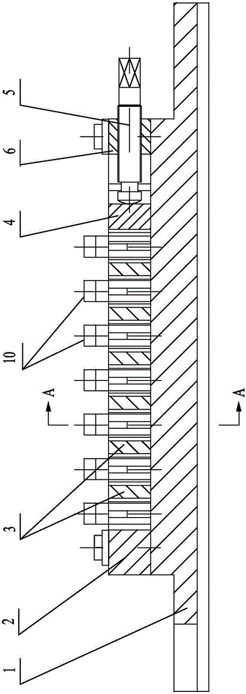
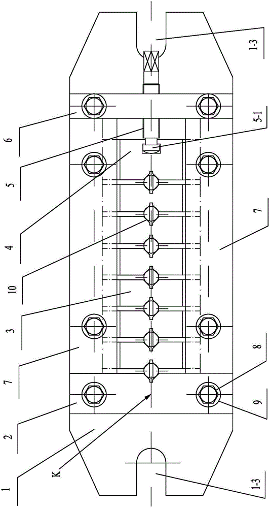
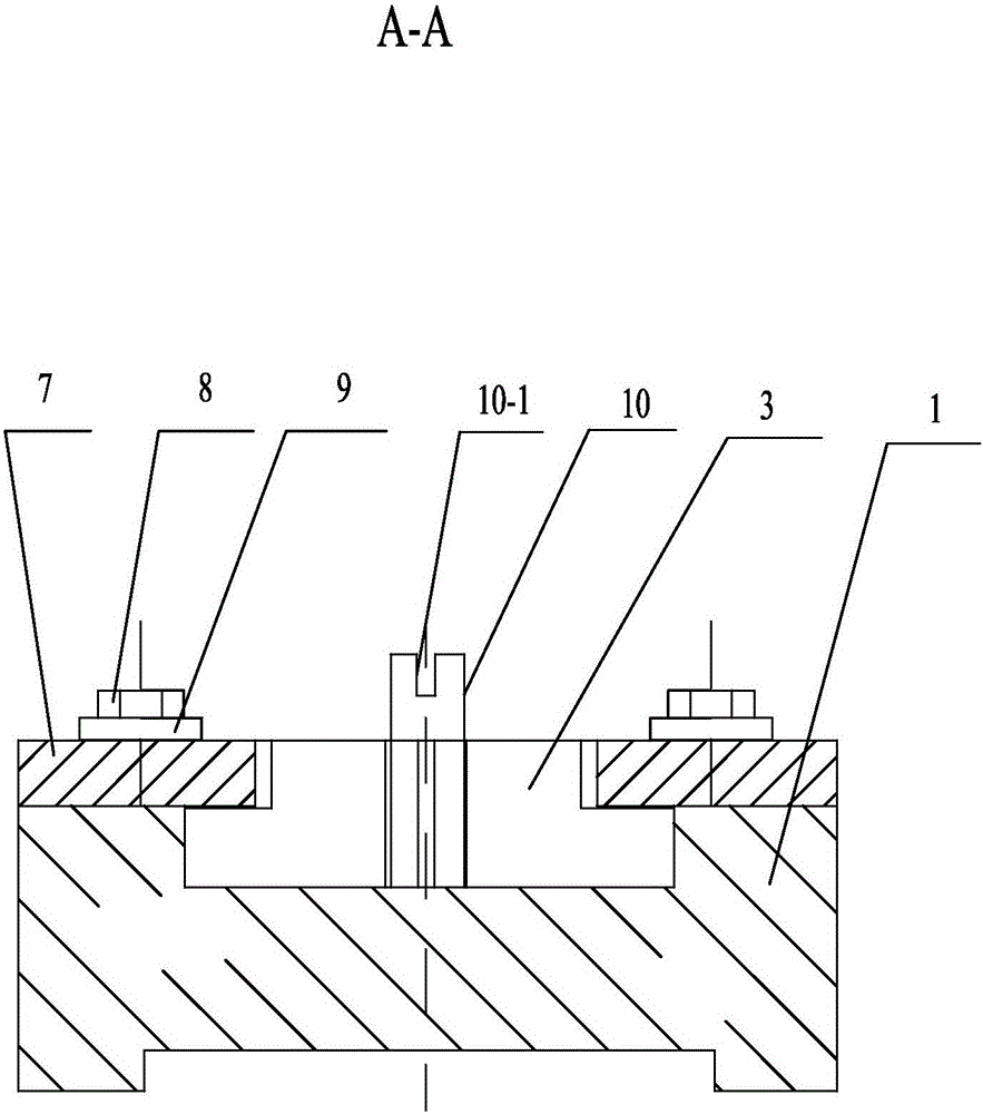
[0021] Specific implementation mode one: combine Figure 1 to Figure 11 Describe this embodiment, the special fixture for end face milling of shaft parts in this embodiment includes a clamp body 1, a positioning block 2, an inverted T-shaped clamping block 4, a jacking screw 5, a baffle plate 6, two pressure plates 7 and a plurality of Inverted T-shaped slider 3, the clamp body 1 includes a base 1-1 and two rectangular bosses 1-2, the two rectangular bosses 1-2 are arranged facing each other and fixed to the upper surface of the base 1-1, and the positioning block 2 and baffle plate 6 are respectively arranged on the both sides of the length direction of two rectangular bosses 1-2, the bottom surface of positioning block 2 and baffle plate 6 are all fixedly connected with base 1-1, the side of positioning block 2 and baffle plate 6 The plate surface of the positioning block 2 is close to the corresponding side faces of the two rectangular bosses 1-2, and the side face opposite...

specific Embodiment approach 2

[0022] Specific implementation mode two: combination figure 2 , Figure 8 and Figure 10 The present embodiment will be described. The longitudinal sections of the plurality of inverted T-shaped sliders 3 in this embodiment are the same in size and shape as the longitudinal sections of the inverted T-shaped clamping block 4 . Such a design can make the inverted T-shaped clamping block 4 fully contact with the inverted T-shaped slider 3, making the clamping more stable. Other components and connections are the same as those in the first embodiment.

specific Embodiment approach 3

[0023] Specific implementation mode three: combination figure 2 Referring to this embodiment, the central sections of the first V-shaped groove 2-1, the plurality of second V-shaped grooves 3-3 and the third V-shaped groove 4-3 in this embodiment are all located in the first plane K. Such a design can ensure that the shaft parts 10 to be processed are located in the same row, which is convenient for slot milling. Other components and connections are the same as those in the second embodiment.


PUM


Abstract

The invention discloses a clamp special for groove milling of end faces of shaft parts, and relates to a clamp. The clamp solves the problems that during groove milling of the end faces of existing shaft parts, only one shaft part can be clamped each time, and the production efficiency is low. According to the clamp, a positioning block and a baffle are arranged on the two sides of two rectangular bosses in the length direction, the opposite side faces of the positioning block and the baffle are each provided with a first V-shaped groove in the height directions of the positioning block and the baffle, and the two sides of each inversed-T-shaped sliding block are each provided with a second V-shaped groove in the height direction of the inversed-T-shaped sliding block; one side of each inversed-T-shaped sliding block is provided with a third V-shaped groove in the height direction of the inversed-T-shaped sliding block, and the sizes of the first V-shaped grooves, the second V-shaped grooves and the third V-shaped grooves are matched with the outer diameter of the to-be-machined shaft parts; and ejection screws penetrate center screw holes to be rotationally connected with inversed-T-shaped clamping blocks, and the multiple inversed-T-shaped sliding blocks and the inversed-T-shaped clamping blocks can slide in zones between two pressing plates and a clamp body. The clamp is used for groove milling of the end faces of the shaft parts.

Description

technical field [0001] The invention relates to a fixture, in particular to a special fixture for end face milling of shaft parts. Background technique [0002] The shaft parts can be clamped by the dividing head when milling grooves on the end face. Although the product quality can be guaranteed, only one piece can be clamped at a time, and the production efficiency is low, which cannot meet the requirements of mass production. Contents of the invention [0003] In order to solve the problem that only one piece can be clamped at a time and the production efficiency is low when milling grooves on the end faces of existing shaft parts, the present invention further proposes a special clamp for end face milling grooves on shaft parts. [0004] The technical solution adopted by the present invention in order to solve the above technical problems is: the special fixture for end face milling of shaft parts of the present invention includes a clamp body, a positioning block, an ...

Claims


Application Information

Patent Timeline
Patent Type & Authority Applications(China)
IPC IPC(8): B23Q3/06
CPCB23Q3/061
Inventor 曾庆富郭楠男温海峰
Owner HARBIN JIANCHENG GRP
Why Eureka
Try Eureka