Stainless steel strip forming equipment for steel-aluminum composite contact rail

A technology of stainless steel strip and steel-aluminum composite, applied in other manufacturing equipment/tools, manufacturing tools, etc., can solve the problem that general equipment cannot meet the requirements of mass production of steel-aluminum composite contact rail, there is no mature special equipment for stainless steel strip processing, bending Technology and high drilling accuracy requirements, etc., to achieve the effect of novel structure, reasonable design and good performance

Inactive Publication Date: 2014-03-05
NANJING JINCHENG RAIL TRANSPORT EQUIP +1
View PDF4 Cites 14 Cited by
  • Summary
  • Abstract
  • Description
  • Claims
  • Application Information

AI Technical Summary

Problems solved by technology

The disadvantages of this kind of equipment are: due to the high requirements on bending technology and drilling precision during processing, the process is complicated, and it cannot be formed at one time, so the product quality and dimensional accuracy are poor; and the efficiency is very low.
So far, there is no mature special equipment for the processing of stainless steel strips for steel-aluminum composite contact rails, and general-purpose equipment cannot meet the requirements for mass production of steel-aluminum composite contact rails

Method used


Image

  • Stainless steel strip forming equipment for steel-aluminum composite contact rail

Examples


Embodiment Construction

[0017] The present invention will be further described below in conjunction with the accompanying drawings and embodiments.

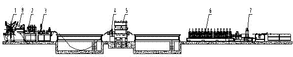
[0018] The special equipment for forming stainless steel strips for steel-aluminum composite contact rails includes uncoiler 1, material leveling machine 2, shearing butt welding platform 3, servo feeder 4, punching machine 5, roll forming unit 6, cut-to-length Machine 7; the uncoiler 1 used to support the unwinding of the stainless steel coil is set on the front side of the lead material leveler 2 that makes the stainless steel coil unwind smoothly and flattens the rolled out steel strip; the shear butt welding platform 3 is set on the lead material leveler The rear side of the flat machine 2; the servo feeder 4 used to control the feeding speed and length is arranged on the front side of the punching machine 5, and the punching machine 5 used for punching holes on both sides of the steel strip passes through the servo feeder 4 and the shearing machine....


PUM


Abstract

The invention discloses stainless steel strip forming equipment for a steel-aluminum composite contact rail. The stainless steel strip forming equipment comprises an uncoiler, a material guide leveler, a cutting butt welding platform, a servo feeder, a punching machine, a roll bending and forming unit, and a sizing and cutting machine. The uncoiler is disposed on the front side of the material guide leveler. The cutting butt welding platform is disposed on the rear side of the material guide leveler. The servo feeder is disposed on the front side of the punching machine. The punching machine used for punching holes on two lateral sides of steel strips is connected with the cutting butt welding platform through the servo feeder. The roll bending and forming unit used for bending and forming two lateral sides of the steel strips is disposed on the rear side of the punching machine. The sizing and cutting machine is disposed on the rear side of the roll bending and forming unit. The stainless steel strip forming equipment is reasonable in design, novel in structure, simple in production procedures, capable of forming at one step and continuously and stably producing, and high in efficiency. The produced stainless steel strips are stable in quality and good in performance, and the requirements of batch production of the stainless steel strips for the steel-aluminum composite contact rail can be satisfied completely.

Description

technical field [0001] The invention relates to a stainless steel strip production equipment, in particular to a stainless steel strip forming equipment for a rail transit steel-aluminum composite contact rail. Background technique [0002] With the rapid development of rail transit, the quality requirements for rail transit steel-aluminum composite contact rail are getting higher and higher. The currently used contact rail for power supply usually consists of a substrate and a brush surface. The brush surface is connected to the substrate, and the brush surface is made of wear-resistant materials. There are stainless steel strips running along the length of the brush face, wherein each steel strip together with a longitudinal elongate side of the brush face part forms a depression which is at least partially filled with the material of the base body. [0003] As an important part of the steel-aluminum composite contact rail, the quality of the stainless steel strip directl...

Claims


Application Information

Patent Timeline
Patent Type & Authority Applications(China)
IPC IPC(8): B23P23/00
CPCB23P23/06
Inventor 高永金张国芳陈雪江左世慧刘国领刘华中张金枝周春临娄亚军赖锦堂赵婷张娴
Owner NANJING JINCHENG RAIL TRANSPORT EQUIP
Why Eureka
Try Eureka