Trial cutting device for analysis of workpiece surface quality problems and analysis method
A technology for quality problems and workpiece surfaces, applied to metal processing machinery parts, manufacturing tools, metal processing equipment, etc., can solve problems such as inaccurate cause location and long processing cycle, and achieve rapid cause finding, accurate cause analysis, and trial cutting Programs are flexible and variable
- Summary
- Abstract
- Description
- Claims
- Application Information
AI Technical Summary
Problems solved by technology
Method used
Image
Examples
Embodiment 1
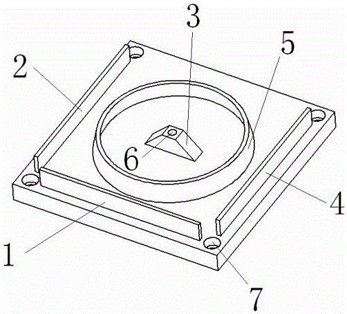
[0035] As a preferred embodiment of the present invention, with reference to the attached figure 1 , this embodiment discloses a workpiece surface quality problem analysis trial cutting device, this embodiment includes:
[0036] A workpiece surface quality problem analysis test cutting device, including a base, the base is rectangular, and the base is equipped with an X-axis test piece 1, a Y-axis test piece 2, a Z-axis test piece 3, an A-axis test piece 4, and a B-axis -C-axis test piece 5 and origin hole 6; the X-axis test piece 1, the Y-axis test piece 2 and the A-axis test piece 4 are all strip-shaped protrusions, and are all parallel to the edge of the base; the X-axis Test piece 1 is set on the edge of the base, Y-axis test piece 2 and A-axis test piece 4 are respectively set on the edge of the base adjacent to X-axis test piece 1; and set in the middle of the base; the origin hole 6 is a blind hole set in the middle of the top plane of the Z-axis test piece 3; the B-ax...
Embodiment 2
[0076] As a preferred embodiment of the present invention, with reference to the attached figure 1 , this embodiment discloses a workpiece surface quality problem analysis trial cutting device, this embodiment includes:
[0077] A workpiece surface quality problem analysis test cutting device, including a base, the base is rectangular, and the base is equipped with an X-axis test piece 1, a Y-axis test piece 2, a Z-axis test piece 3, an A-axis test piece 4, and a B-axis -C-axis test piece 5 and origin hole 6; the X-axis test piece 1, the Y-axis test piece 2 and the A-axis test piece 4 are all strip-shaped protrusions, and are all parallel to the edge of the base; the X-axis Test piece 1 is set on the edge of the base, Y-axis test piece 2 and A-axis test piece 4 are respectively set on the edge of the base adjacent to X-axis test piece 1; and set in the middle of the base; the origin hole 6 is a blind hole set in the middle of the top plane of the Z-axis test piece 3; the B-ax...
Embodiment 3
[0080] As a preferred embodiment of the present invention, with reference to the attached figure 1 , this embodiment discloses a method for analyzing and trying to cut workpiece surface quality problems, this embodiment includes:
[0081] A workpiece surface quality problem analysis test cutting device, including a base, the base is rectangular, and the base is equipped with an X-axis test piece 1, a Y-axis test piece 2, a Z-axis test piece 3, an A-axis test piece 4, and a B-axis -C-axis test piece 5 and origin hole 6; the X-axis test piece 1, the Y-axis test piece 2 and the A-axis test piece 4 are all strip-shaped protrusions, and are all parallel to the edge of the base; the X-axis Test piece 1 is set on the edge of the base, Y-axis test piece 2 and A-axis test piece 4 are respectively set on the edge of the base adjacent to X-axis test piece 1; and set in the middle of the base; the origin hole 6 is a blind hole set in the middle of the top plane of the Z-axis test piece 3...
PUM
 Abstract
Description
Claims
Application Information
 - R&D
- Intellectual Property
- Life Sciences
- Materials
- Tech Scout
- Unparalleled Data Quality
- Higher Quality Content
- 60% Fewer Hallucinations
Browse by: Latest US Patents, China's latest patents, Technical Efficacy Thesaurus, Application Domain, Technology Topic, Popular Technical Reports.
© 2025 PatSnap. All rights reserved.Legal|Privacy policy|Modern Slavery Act Transparency Statement|Sitemap|About US| Contact US: help@patsnap.com

