
Die and compression forming method for composite-material formed parts

A technology for composite materials and molded parts, applied in the field of composite material forming molds, can solve problems such as difficulty in mold clamping, difficulty in female mold clamping, and difficulty in female mold annular clamping.

Inactive Publication Date: 2016-06-29
HARBIN
View PDF6 Cites 8 Cited by
  • Summary
  • Abstract
  • Description
  • Claims
  • Application Information

AI Technical Summary

Problems solved by technology

[0004] The male and female modules of the existing metal dies use the same metal material, and the gap between the inner and outer modules is the theoretical thickness of the product, that is, the solidified thickness, which is smaller than the layer thickness (the thickness just laid before the mold is closed), so the female mold Ring mold clamping is very difficult; in order to solve the difficulty of mold clamping, it is necessary to increase the cavity gap, that is, the gap between the male and female molds, and it is necessary to invent a metal molding structure to solve the difficult problem of female mold clamping

Method used


Image

  • Die and compression forming method for composite-material formed parts
  • Die and compression forming method for composite-material formed parts
  • Die and compression forming method for composite-material formed parts

Examples


Embodiment Construction

[0018] A mold is provided, especially a mold for a composite material molding, including a female mold and a male mold, the materials of the female mold and the male mold are different, the coefficient of thermal expansion of the female mold is smaller than that of the male mold, and the coefficient of thermal expansion of the female mold is the same as The ratio of the coefficient of thermal expansion of the male die is 1:13 to 1:11.

[0019] Provided is a compression molding method for a composite material molding, comprising the steps of:

[0020] Step 1. Mold preparation

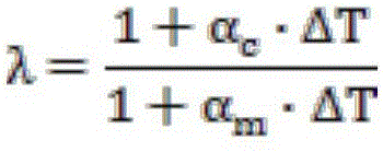
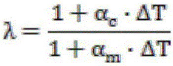
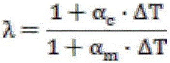
[0021] Use CATIA modeling software to obtain the model of the molded part, and calculate the female mold model and the male mold model according to the model of the molded part and the formula of the reduction coefficient, and then process the female mold according to the female mold model and the male mold model Mold and positive die mold, the formula of the reduction factor is:

[0022] ...


PUM


Abstract

The invention relates to a die and a compression forming method for composite-material formed parts. The technology disclosed by the invention is characterized in that a gap between a female die and a male die is increased and greater than the theoretical thickness of products; the female die is made from a material with a low thermal expansion coefficient, for example, invar steel; the male die is made from a material with a high thermal expansion coefficient, for example, aluminium alloy; in order to guarantee that the die achieves correct product dimensions (the shape of the male die and the shape of the female die) at a curing temperature, the normal-temperature dimensions of the die need to be reduced according to the respective shrinkage ratio coefficients of the female die and the male die respectively; the dimension shrinkage amount of the female die is low, and the dimension shrinkage amount of the male die is high, therefore, the normal-temperature gap between the female die and the male die is increased; and during curing heating, the expansion amount of the male die is high, a die cavity gap is reduced, a laying layer is pressed towards the female die, and a metal expansion compression effect is achieved. After curing is concluded, the die starts to cool, the shrinkage amount of the male die is high; and the laying layer is already cured into a composite material, and because the thermal expansion coefficient of the composite material is low, and the shrinkage amount of each composite-material product is low, the male die is separated from the product, and an automatic die release effect is achieved.

Description

technical field [0001] The invention belongs to the field of composite material molding dies. Background technique [0002] The solidification and molding of composite material components requires heating and pressure. Generally, a single mold (one side is a solid mold and the other side is a vacuum bag) is used to ensure compaction, such as a composite skin. The existing composite material reinforcement frame has two cavities located on both sides of the web surface, and the vacuum bag pressurization cannot be realized by using a single mold, and a combined mold is required. After the existing combined mold formed by the positive mold is formed and cured, the outer surface of the frame edge becomes orange peel folds, which cannot meet the assembly requirements; the reason is that the frame edge is relatively thick; the prepreg resin content is high; when the curing pressure is applied from the outside to the inside At the same time, the fibers placed in the ring move towar...

Claims


Application Information

Patent Timeline
Patent Type & Authority Applications(China)
IPC IPC(8): B29C70/44B29C33/44
CPCB29C70/44B29C33/44
Inventor 岳旭
Owner HARBIN
Learn More