
A control device for an automatic transmission vehicle

A technology of automobile control and automatic transmission, which is applied to the safety device of the power plant control mechanism, the layout of the power plant control mechanism, and motor vehicles, and can solve problems such as difficult operation, easy false start, and automobile braking to achieve safety High performance, good compatibility and simple structure

Active Publication Date: 2018-07-06
邱伦厚
View PDF8 Cites 0 Cited by
  • Summary
  • Abstract
  • Description
  • Claims
  • Application Information

AI Technical Summary

Problems solved by technology

According to the search, it is found that a certain invention adopts the method of installing sensors and voice sensors on the right spoke of the steering wheel for error prevention and error correction. The shortcoming of this invention is that the position of the sensor installed on the right spoke of the steering wheel will change with the position of the steering wheel. It is not easy to operate in an emergency, and it is easy to activate the device by mistake during normal driving, and the car will automatically brake after the device is activated by mistake, which may cause new serious consequences

Method used


Image

  • A control device for an automatic transmission vehicle
  • A control device for an automatic transmission vehicle
  • A control device for an automatic transmission vehicle

Examples


Embodiment 1

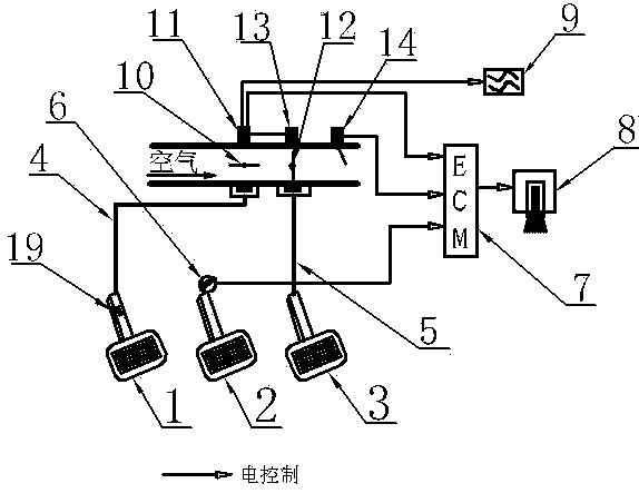
[0008] Embodiment 1: a kind of automatic gear car control device, see figure 2 , there is an auxiliary pedal 1 at the left foot position, and the auxiliary pedal 1 can be folded up and hidden or disassembled through the pin 19, and there is an accelerator pedal 3 at the right foot position, and there is a brake pedal 2 between the auxiliary pedal 1 and the accelerator pedal 3. Pedal 1 is connected with auxiliary pedal accelerator line 4, which can control the opening and closing of auxiliary throttle valve 10, and the auxiliary throttle valve 10 is in a normally open state. In the normally closed state, the main throttle position sensor 13 can sense the switch position of the main throttle valve 12, and the auxiliary throttle position sensor 11 can sense the switch position of the auxiliary throttle valve 10, and can compare the auxiliary throttle position sensor 11 with the main throttle position sensor. The throttle position sensor 13 senses the signal for selection. When t...

Embodiment 2

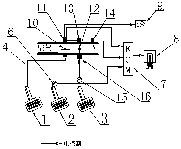
[0009] Embodiment 2: a kind of automatic gear car control device, see image 3 , there is an auxiliary pedal 1 at the left foot position, an accelerator pedal 3 at the right foot position, and a brake pedal 2 between the auxiliary pedal 1 and the accelerator pedal 3. The auxiliary pedal 1 is connected with the auxiliary pedal accelerator line 4, which can control the Valve 10 switch, sub-throttle valve 10 is normally open state, accelerator pedal 3 is connected with accelerator pedal position sensor 15, can control main throttle valve 12 switch by accelerator pedal actuator 16, main throttle valve 12 is normally closed state, main throttle valve The position sensor 13 can sense the switch position of the main throttle valve 12, and the secondary throttle position sensor 11 can sense the switch position of the secondary throttle valve 10, and can sense signals from the secondary throttle position sensor 11 and the primary throttle position sensor 13. Optionally, when the auxili...

Embodiment 3

[0010] Embodiment 3: a kind of automatic gear car control device, see Figure 4 , there is an auxiliary pedal 1 at the left foot position, an accelerator pedal 3 at the right foot position, a brake pedal 2 is located between the auxiliary pedal 1 and the accelerator pedal 3, the auxiliary pedal 1 is connected to an auxiliary pedal position sensor 17, and the accelerator pedal 3 is connected to There is an accelerator pedal position sensor 15, and the pre-processor 18 selects the output signals of the auxiliary pedal position sensor 17 and the accelerator pedal position sensor 15. When the auxiliary pedal 1 is fully released, the pre-processor 18 selects the output signal of the accelerator pedal position sensor 15. The output signal is sent to the main throttle actuator 16. When the auxiliary pedal 1 is depressed, the preprocessor 18 selects the auxiliary pedal position sensor 17 to output the signal to the main throttle actuator 16 to control the opening and closing of the mai...


PUM


Abstract

The invention relates to an automatic transmission automobile control device.A foldable or detachable auxiliary pedal is arranged at the position of the left foot, an accelerator pedal is arranged at the position of the right foot, a brake pedal is arranged between the auxiliary pedal and the accelerator pedal, and the rotating speed of an engine can be controlled by the auxiliary pedal and the accelerator pedal jointly; on the premise that the auxiliary pedal is in the completely released state, the rotating speed of the engine is idle speed V1 when the accelerator pedal is completely released, and the rotating speed of the engine is V10 when the accelerator pedal is completely treaded down; when the accelerator pedal is in any state, the rotating speed of the engine is V0 when the auxiliary pedal is completely treaded down, V0 can be smaller than or equal to V1 and can also be slightly larger than V1, and the rotating speed of the engine can be gradually increased and can also be stay at V0 when the auxiliary pedal is released; the brake pedal can be combined with the auxiliary pedal and the accelerator pedal to control the rotating speed of the engine or not, and prompt signals in the form of sound, light, vibration and the like can be output according to the treading positions of the auxiliary pedal, the accelerator pedal and the brake pedal.

Description

technical field [0001] The invention belongs to the automobile driving control technology and relates to the improvement of an automatic transmission automobile driving control device. Background technique [0002] At present, there are two main modes of the automobile driving control device, one is a manual transmission control mode, and the other is an automatic transmission control mode. There are three pedals that need to be controlled by the foot in a manual transmission car, namely the clutch pedal, the brake pedal and the accelerator pedal. The function of the clutch pedal is to control the separation and connection of the engine output and the wheel drive. Depress the clutch pedal first and then the brake pedal to prevent stalling. If the accelerator pedal is pressed by mistake while the clutch pedal is fully depressed, the engine will idle at high speed and produce roar and vibration, but the car will not move rapidly due to the accelerator pedal being depressed, a...

Claims


Application Information

Patent Timeline
Patent Type & Authority Patents(China)
IPC IPC(8): B60K26/02B60K28/00
CPCB60K26/02B60K28/00
Inventor 不公告发明人
Owner 邱伦厚
Learn More