Calibration method of laser seam tracking sensor

A calibration method and sensor technology, applied in the field of sensor calibration, can solve problems such as difficulty in obtaining three-dimensional punctuation points, and achieve the effects of reducing the probability of human error, high precision, and simple experiments

Inactive Publication Date: 2018-01-12
CHINA JILIANG UNIV
View PDF7 Cites 0 Cited by
  • Summary
  • Abstract
  • Description
  • Claims
  • Application Information

AI Technical Summary

Problems solved by technology

Among them, how to obtain a sufficient number of high-precision calibration points in 3D space is the difficulty of the whole calibration system, mainly because it is difficult for the known 3D world points on the target to be exactly located on the structured light plane, so that the acquisition of 3D punctuation points is difficult. become difficult

Method used


Image

  • Calibration method of laser seam tracking sensor
  • Calibration method of laser seam tracking sensor
  • Calibration method of laser seam tracking sensor

Examples


Embodiment Construction

[0015] The present invention will be further described below in conjunction with the accompanying drawings and specific embodiments.

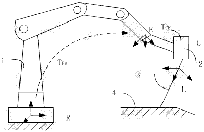
[0016] (1) Laser welding seam scanning tracking sensor system

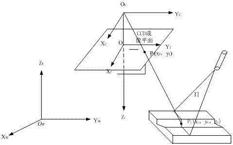
[0017] Such as figure 1 As shown, the laser scanning seam tracking sensor system is mainly composed of a laser seam tracking sensor 2 and a six-degree-of-freedom robot 1 . The laser seam tracking sensor is fixed at the end of the robot, and is controlled by the mechanical arm to detect the seam surface 4, using a straight-line structured light 3. The coordinate systems involved in this system are as follows. In the figure, {R} is the basic coordinate system fixedly connected to the robot base; {E} is the coordinate system of the degree of freedom at the end of the manipulator; {C} is the laser plane coordinate system. The equivalent optical path diagram is as follows figure 2 shown.

[0018] Camera coordinate system: camera focal length center point O c The coordinate system ...


PUM


Abstract

The invention discloses a laser-welding seam tracking sensor calibration method.The method comprises the steps that a black-and-white checkerboard is put on a white background; the laser plane intersects with checkerboard diagonal angular points by adjusting camera space positions and postures; three sets of angular point coordinates obtained through the space positions and postures meeting the requirements are taken; angular point coordinates in a target coordinate system are calculated according to a matrix transformation relationship of the angular points relative to the target coordinate system; a linear equation on one laser plane is obtained through one set of angular point coordinates.Straight lines on three laser planes can be obtained by three sets of data, and the laser plane in a camera coordinate system is obtained according to any two linear equations; the whole calibration process is completed.The applied sensor calibration technology has the advantages of being simple in experiment, high in precision, high in speed and the like.

Description

technical field [0001] The invention relates to a sensor calibration method in an intelligent robot laser seam tracking system. The sensor calibration includes camera calibration and structure cursor calibration. Background technique [0002] Laser sensor welding technology is widely used in the field of industrial welding due to its advantages of high precision, high speed, and strong adaptability. During the welding process of the laser sensor, uncertain factors such as the error of the pre-installed material and the deformation of the weld seam caused by the thermal stress during the welding process will cause changes in the position and size of the joint. The traditional way of teaching welding through industrial robots can no longer meet the precision requirements of industrial welding, so it is necessary to introduce a seam tracking system. The structured light vision sensor has the characteristics of high measurement accuracy, large amount of information, and high se...

Claims


Application Information

Patent Timeline
Patent Type & Authority Patents(China)
IPC IPC(8): G01B11/00G01B11/24G01B11/30B23K26/70
CPCB23K26/702G01B11/002G01B11/24G01B11/30
Inventor 唐琛张斌
Owner CHINA JILIANG UNIV
Why Eureka
Try Eureka