Rapid high-precision 3D shape measuring method

A measurement method and high-precision technology, applied in the direction of measuring devices, instruments, optical devices, etc., can solve the problems of inaccurate boundary extraction and low measurement efficiency

Active Publication Date: 2016-06-29
DALIAN UNIV OF TECH
View PDF11 Cites 23 Cited by
  • Summary
  • Abstract
  • Description
  • Claims
  • Application Information

AI Technical Summary

Problems solved by technology

[0003] The technical problem to be solved by the present invention is to solve the problem of low measurement efficiency and inaccurate boundary extraction in the process of measuring the three

Method used


Image

  • Rapid high-precision 3D shape measuring method
  • Rapid high-precision 3D shape measuring method
  • Rapid high-precision 3D shape measuring method

Examples


Embodiment 1

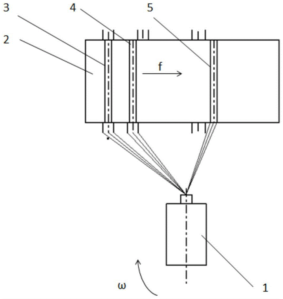
[0043] Embodiment 1, according to the present invention, two cameras respectively equipped with wide-angle lenses capture a light strip image. The camera model is vieworksVC-12MC-M / C65 camera, resolution: 4096×3072, image sensor: CMOS, frame rate: full frame, maximum 64.3fps, weight: 420g. The wide-angle lens model is EF16-35mmf / 2.8LIIUSM, the parameters are as follows, lens focal length: f=16-35, APS focal length: 25.5-52.5, aperture: F2.8, lens size: 82×106. The shooting conditions are as follows: the picture pixel is 4096×3072, the focal length of the lens is 17mm, the object distance is 750mm, and the field of view is about 800mm×800mm.

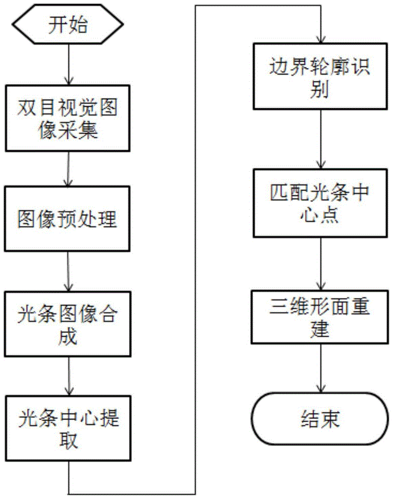
[0044] attached image 3 It is a flow chart of three-dimensional surface measurement. The measurement process of the whole 3D shape includes image acquisition, light strip image denoising and synthesis, light strip center extraction, boundary contour recognition, matching light strip center point and reconstruction of 3D shape. Accordi...


PUM


Abstract

The invention relates to a 3D shape measuring method by identifying a boundary on the basis of abrupt change of the light stripe width, and belongs to the technical field of computer vision measurement. Light stripe images collected by a binocular visual measurement system are denoised in a difference image method, the light stripe width is changed in the boundary contour according to that reflection characteristics of laser stripes in the surfaces of objects of different materials are different, the boundary position is identified accurately according to change of the light stripe width, light strip information within the boundary is matched and reconstructed, and the 3D shape is measured rapidly in high precision. The measuring method comprises the steps of collection of images, denoising and synthesis of the light stripe images, extraction of the center of the light stripes, identification of the boundary contour, matching of the central points of the light stripes and reconstruction of the 3D shape. The method is high in measuring precision, reduces the redundancy computational complexity, improves the processing efficiency, and can meet requirements of rapid high-precision 3D shape measurement for general large composite components.

Description

technical field [0001] The invention belongs to the technical field of computer vision measurement, and relates to a three-dimensional surface measurement method based on the sudden change in the width of light strips to identify boundaries Background technique [0002] With the rapid development of manufacturing technology in the aerospace field, automobile industry, molds and major equipment parts, people have put forward higher requirements for the precision and quality of manufacturing. For example, the high-precision measurement of the three-dimensional shape of large parts such as the plane and vertical tail of the aircraft. Due to the large size, irregular shape, and high local precision requirements of such parts, the accurate measurement of the three-dimensional shape has become a difficult problem. In recent years, the binocular vision measurement method based on structured light scanning has become a research hotspot for researchers. Because this method has the a...

Claims


Application Information

Patent Timeline
IPC IPC(8): G01B11/24
CPCG01B11/2433
Inventor 刘巍兰志广高鹏杨帆张洋李晓东贾振元高航
Owner DALIAN UNIV OF TECH
Why Eureka
Try Eureka