
A bolt simulator structure

A simulator and bolt technology, applied in the field of measuring equipment testing, can solve problems such as misjudgment of torque wrench error indicators, affecting product quality, and large number of configurations, achieving stable and reliable performance, reducing the number of configurations, and improving stability and repeatability Effect

Inactive Publication Date: 2018-07-06
HUNAN LUOYOU ENGINE PARTS
View PDF8 Cites 5 Cited by
  • Summary
  • Abstract
  • Description
  • Claims
  • Application Information

AI Technical Summary

Problems solved by technology

However, due to the narrow torque range that can be simulated by disc springs, a large number of bolt simulators with different torque ranges are required, so the number of configurations is large, the consistency is poor when reproducing the torque value, and large errors are prone to occur, which will affect the torque value. Misjudgment of the wrench error index, which indirectly affects product quality

Method used


Image

  • A bolt simulator structure
  • A bolt simulator structure
  • A bolt simulator structure

Examples


Embodiment 1

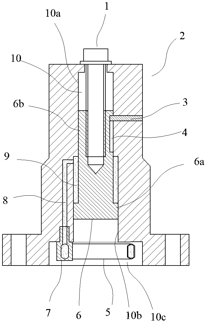
[0020] Such as figure 1 In the shown embodiment, a bolt simulator structure includes a base 2 and a transmission bolt 1, a vertical inner hole 10 is arranged in the base, a relatively slidable piston 6 is arranged in the inner hole, and the threaded end of the transmission bolt It is threadedly connected with the upper end of the piston, and the head of the transmission bolt abuts against the upper surface of the base. A guide groove 4 arranged axially is arranged on the piston, and a guide pin 4 slidingly matched with the guide groove is arranged in the base. When the transmission bolt is turned, the threaded end of the transmission bolt and the upper end of the piston are gradually screwed tightly, thereby driving the piston to move upward.

[0021] The inner hole in the base is a stepped hole, including a connected upper hole 10a and a lower hole 10b. The diameter of the upper hole is smaller than the diameter of the lower hole. The piston is provided with an upper hole se...

Embodiment 2

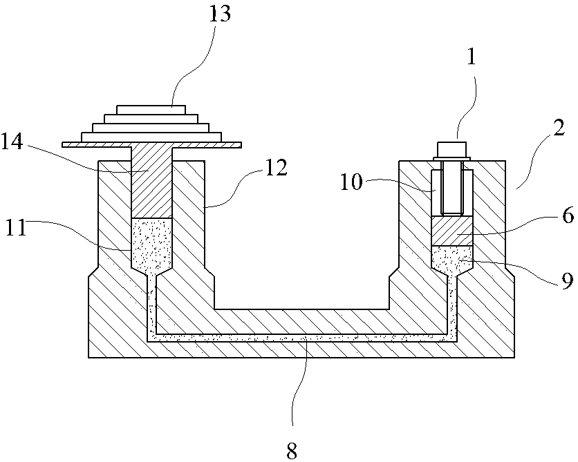
[0024] Such as image 3 As shown, a bolt simulator structure includes a base and a transmission bolt. The base is provided with a vertical inner hole, and a relatively slidable piston is arranged in the inner hole. The transmission bolt is against the surface of the piston. The positioning part that is threaded with the transmission bolt forms an oil pressure chamber between the piston and the inner hole. When the transmission bolt rotates, the piston is pushed down to compress the oil pressure chamber. The base is provided with an oil passage connected with the oil pressure chamber, and the oil passage is connected with a counter force device, which includes a tray 14 and a weight group 13 placed on the tray, and a tray support seat 12 is provided on the base, and the tray supports An oil outlet passage 11 communicating with the oil passage is arranged in the seat, and the oil outlet passage is vertically arranged, and a pallet piston slidingly matched with the oil outlet pas...


PUM


Abstract

The invention discloses a bolt simulator structure comprising a pedestal and a transmission bolt. The pedestal is provided with a vertical inner hole, in which is disposed a piston capable of carrying out relative sliding motion. A sealed oil pressure chamber can be formed between the piston and the inner hole. The transmission bolt is used to act on the upper end of the piston to drive the piston to move axially. The pedestal is provided with an oil channel communicated with the oil pressure chamber, and the oil channel is connected with a counter-force device, which is used to provide the counter force for the oil pressure chamber. A torque spanner sleeve is connected with the transmission bolt of the simulator. The object of the invention is to provide the bolt simulator structure capable of providing wide torque range and reducing configuration quantity.

Description

technical field [0001] The invention belongs to the field of measuring equipment test, in particular to a bolt simulator structure. Background technique [0002] At present, pneumatic or electric torque wrenches and torque tightening machines are widely used in the field of automobile assembly, engine and transmission assembly. During the long-term frequent use of the torque wrench, the preset torque value may change, which requires regular adjustment of the torque wrench. Perform a check calibration. The torque test of the torque wrench can be checked by a bolt simulator. At present, the bolt simulators on the market are of disc spring type, such as the Chinese patent announcement number: CN203672603U, which discloses the bolt simulation mechanism in the torque tool detection device, including Bolt simulator and sensor assembly; the bolt simulator includes a shell, a square threaded sleeve, a disc spring, a locking extrusion assembly and a limit ring; the inside of the she...

Claims


Application Information

Patent Timeline
Patent Type & Authority Patents(China)
IPC IPC(8): G01L5/24G01M13/00
CPCG01L5/24G01M13/00
Inventor 王国友姚本顺黄建华李美平王瑞平
Owner HUNAN LUOYOU ENGINE PARTS
Learn More