
Atmospheric correction refractive index state distribution integrated verification system

A technology of atmospheric correction and verification system, which is applied in the fields of analyzing materials, conducting material analysis by optical means, and measuring phase influence characteristics. Lack of problems such as setting up an environmental analysis system to achieve the effect of strong adaptive networking capability, wide application range and high degree of intelligence

Inactive Publication Date: 2016-06-29
田斌 +9
View PDF3 Cites 7 Cited by
  • Summary
  • Abstract
  • Description
  • Claims
  • Application Information

AI Technical Summary

Problems solved by technology

Although the existing meteorological instruments can obtain the spatial distribution information of data such as temperature, air pressure, and relative humidity in the atmospheric environment, and then obtain the preliminary atmosphere-corrected refractive index situation distribution through related formulas, the above-mentioned equipment has the advantages of data integrity, relevance, There are certain deficiencies in real-time and other aspects. At the same time, the above-mentioned instruments lack a relevant analysis system for evaluating the erection environment, so that it is impossible to accurately grasp the influence of the sensor erection environment on the instrument, and it is also impossible to accurately select the erection environment. The above situation will be As a result, the collected data cannot accurately reflect the spatial situation distribution of the atmospheric corrected refractivity, making it difficult to use the data as an important standard reference information for atmospheric duct diagnostic analysis, atmospheric duct numerical forecasting, etc.

Method used


Image

  • Atmospheric correction refractive index state distribution integrated verification system
  • Atmospheric correction refractive index state distribution integrated verification system
  • Atmospheric correction refractive index state distribution integrated verification system

Examples


Embodiment Construction

[0022] The following will clearly and completely describe the technical solutions in the embodiments of the present invention with reference to the accompanying drawings in the embodiments of the present invention. Obviously, the described embodiments are only some, not all, embodiments of the present invention. Based on the embodiments of the present invention, all other embodiments obtained by persons of ordinary skill in the art without making creative efforts belong to the protection scope of the present invention.

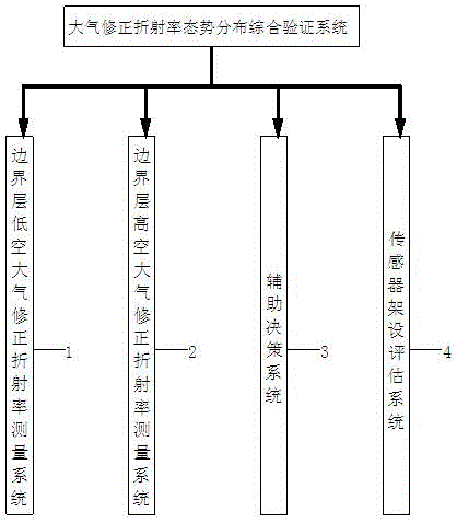
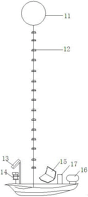
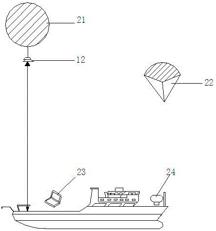
[0023] Please refer to the attached Figure 1-5 , in an embodiment of the present invention, a comprehensive verification system for atmospheric corrected refractive index situation distribution, including a boundary layer low-altitude atmospheric corrected refractive index measurement system 1, a boundary layer mid-high altitude atmospheric corrected refractive index measurement system 2, an auxiliary decision-making system 3 and sensor erection Evaluation Sy...


PUM


Abstract

The invention discloses a comprehensive verification system for atmospheric correction refractive index situation distribution, which includes a boundary layer low-altitude atmospheric correction refractive index measurement system, a boundary layer mid-high altitude atmospheric correction refractive index measurement system, an auxiliary decision-making system and a sensor erection evaluation system; the boundary The low-altitude atmospheric correction refractivity measurement system includes a tethered sounding ball, an atmospheric correction refractivity sensor, a ship-borne infrared temperature sensor, a ship-borne temperature, humidity and pressure sensor, a first control computer, a first Beidou communication module and a ship-borne automatic Meteorological station; the atmospheric correction refractive index situation distribution comprehensive verification system has the characteristics of wide application range, high degree of intelligence, and strong sensor adaptive networking ability. The impact of different platform positions on the data collected by the sensor enables researchers to select a reasonable installation location based on the analysis results and collect more accurate test data.

Description

technical field [0001] The invention relates to a comprehensive verification system for atmospheric correction refractivity situation distribution, which is used in the ocean boundary layer atmosphere, and the collected atmospheric correction refractivity results can be used in research related to the effectiveness of information equipment such as communication, radar, and electronic interference. Background technique [0002] Atmospheric corrected refractive index is an important parameter to characterize the intensity of the atmosphere's refraction of electromagnetic waves, derived from the concept of atmospheric refractive index. In the actual boundary layer atmosphere environment, the atmospheric correction refractive index presents different distribution forms, so that the boundary layer atmosphere has different refraction effects on the electromagnetic waves propagating in it, and then makes the propagation trajectory, direction, energy attenuation and uniformity of the...

Claims


Application Information

Patent Timeline
IPC IPC(8): G01N21/41
CPCG01N21/41G01N2021/4106
Inventor 田斌察豪刘峰刘亚杰李杰崔萌达张显峰路君董素芳杨彤
Owner 田斌
Learn More