Complex pull-out mechanism

A compound and unified technology, applied in the field of machinery, can solve the problems of difficult bearing disassembly, damage to the bearing seat or shaft, and poor disassembly effect, so as to achieve the effect of saving time and labor, high use efficiency and simple manufacturing process for disassembly.

Inactive Publication Date: 2016-07-06
吴玉林
View PDF8 Cites 4 Cited by
  • Summary
  • Abstract
  • Description
  • Claims
  • Application Information

AI Technical Summary

Problems solved by technology

Due to the interference fit between the bearing and the shaft or bearing seat, it is difficult to disassemble the bearing, and the disassembly effect is often not good
In order to remove the outer ring of the bearing and the three-wheel half-shaft, there are three methods for dismantling the outer ring of the half-shaft and the bearing in the prior art: 1. Directly disassemble the gearbox. Oil leaks easily and can cause damage to bearing housings or shafts
2. When disassembling the pull hammer, the thread of the half shaft is easy to be damaged due to the large impact force. If the thread of the half shaft is damaged, the half shaft cannot be disassembled, and the outer ring of the bearing cannot be disassembled.
3. Patent No. 201420403709.1 is a utility model patent titled "A Half-shaft and Bearing Dismounting Device and a Bearing Outer Ring Dismounting Device", which is determined by the design structure of the patent and cannot be used when the half-shaft thread is damaged. The screw adopts a single right-handed thread, and the nut can only be rotated under dry friction to pull out the half shaft, which is difficult to operate. When the outer ring of the bearing is to be pulled out, the matching chuck must be replaced, which is low in work efficiency and poor in applicability

Method used


Image

  • Complex pull-out mechanism
  • Complex pull-out mechanism
  • Complex pull-out mechanism

Examples


Embodiment 1

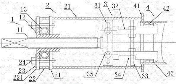
[0031] Bearing outer ring pull-out mechanism.

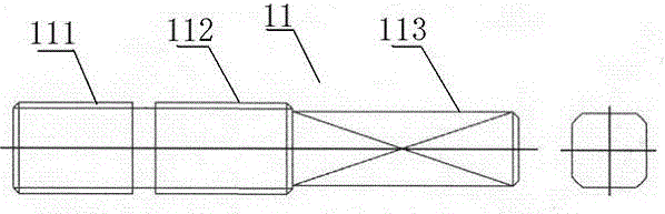
[0032] The present invention as figure 1 , image 3 , Figure 5 , Figure 6 , Figure 7 , Figure 8 , Figure 9 Shown, the bearing outer ring pull-out mechanism. It includes a transmission component 1, a support component 2, a linkage component I and a bearing outer ring component 4. The transmission assembly 1 includes a lead screw 11 , a lead screw nut 12 and a thrust ball bearing 13 . The lead screw 11 is a double-handed equal-pitch thread structure, the thrust ball bearing 13 is sleeved on the lead screw nut 12 , and the lead screw nut 12 is matched and screwed to the left-hand thread section 112 of the lead screw 11 .

[0033] The support assembly 2 includes a support cylinder 21 , a support cylinder cover 211 symmetrically arranged up and down on the support cylinder 21 , an anti-rotation cover seat 22 and an anti-rotation cover 221 . A washer 23 is provided on the anti-rotation cover plate 221 to limit the axial s...

Embodiment 2

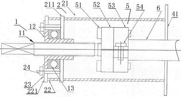
[0037] Half shaft pull-out mechanism.

[0038] The present invention as figure 1 , figure 2 , image 3 , Figure 4 , Figure 5 , Figure 6 , Figure 8 , Figure 10 as shown,

[0039] A half-shaft pull-out mechanism, the transmission assembly 1 and the support assembly 2 have the same structure as that of embodiment 1,

[0040]The difference is that a linkage assembly II is also provided, and the linkage assembly II includes a connecting pull plate 52 and a split nut 53 . The connecting pull plate 52 is screwed to the right-handed thread section 111 of the lead screw 11, and the two ends of the connecting pull plate 52 are detachably and fixedly connected to the two ends of the split nut 53 through the screw rod III, and the split nut 53 is screwed on the half shaft 6 On, the screw rod IV is used to connect the upper and lower parts of the half nut 53.

[0041] The present invention is manufactured by forging and machining.

[0042] The material used for the screw, ...


PUM


Abstract

The invention discloses a complex pull-out mechanism. The complex pull-out mechanism comprises a bearing outer ring pull-out mechanism and a half shaft pull-out mechanism, and the bearing outer ring pull-out mechanism and the half shaft pull-out mechanism are arranged on a same supporting component (2) and in transmission connection with a same transmission component (1). The bearing outer ring pull-out mechanism further comprises a linkage component I and a bearing outer ring component (4), and the half shaft pull-out mechanism comprises a linkage component II and a half shaft (6). A screw rod (11) in the transmission component (1) is in a double-screw-direction thread structure, a left-hand thread section (112) of the screw rod (11) is in matched screw connection with the transmission component (1), and a right-hand thread section (111) of the screw rod (11) is in matched screw connection with the linkage component I or the linkage component II. The complex pull-out mechanism has the advantages of reasonable structural design, simple manufacturing process, convenience in use, safety, reliability, effectiveness in production efficiency improvement and significant reduction of production and use costs.

Description

technical field [0001] The invention belongs to the technical field of machinery, and relates to a dismantling tool, in particular to a repair tool for an electric tricycle, and in particular to a composite pull-out mechanism. Background technique [0002] At present, in mechanical maintenance operations, especially in the case of tricycle half shafts and bearing damage. Due to the interference fit between the bearing and the shaft or bearing seat, it is difficult to disassemble the bearing, and the disassembly effect is often not good. In order to remove the outer ring of the bearing and the three-wheel half-shaft, there are three methods for dismantling the outer ring of the half-shaft and the bearing in the prior art: 1. Directly disassemble the gearbox. Oil leaks easily and can cause damage to the housing or shaft. 2. When disassembling the pull hammer, the thread of the half shaft may be damaged due to the large impact force. If the thread of the half shaft is damaged...

Claims


Application Information

Patent Timeline
Patent Type & Authority Applications(China)
IPC IPC(8): B25B27/073
CPCB25B27/062
Inventor 吴玉林吴熠逊
Owner 吴玉林
Why Eureka
Try Eureka