
Metal workpiece mark printing device

A technology for printing devices and metal workpieces, applied in printing, stamping and other directions, can solve problems such as affecting construction, increasing production costs, and strengthening overall structural strength.

Active Publication Date: 2016-07-06
余敏守
View PDF10 Cites 2 Cited by
  • Summary
  • Abstract
  • Description
  • Claims
  • Application Information

AI Technical Summary

Problems solved by technology

[0003] However, the general way of marking on the surface of steel is to mark directly on the surface of steel with paint or ink. However, general steel needs to be galvanized and anti-rust on the surface before assembly, that is, the steel must be degreased, acid The process of washing, cleaning agent and hot-dip galvanizing can ensure the anti-corrosion effect of the steel. After a series of anti-rust treatments, the markings made of paint or ink will produce a large amount of wear and tear, and make the markings become inconspicuous or indistinct. Accurate, which may cause misjudgment during assembly and construction, affecting subsequent construction
[0004] In addition, there are also operators who make markings on the surface of the steel by etching, but the depth of the markings made by etching is too shallow, so in the process of antirust treatment, the process of immersion plating will fill the plating layer in the etching. In the groove, it will also cause inconspicuous and unclear markings; and once the depth of etching is to be changed, the construction hours will be greatly increased, resulting in a significant increase in production costs; even, in order to strengthen the surface strength of steel. A sandblasting process is carried out, and the above markings made by ink or etching will become more blurred and difficult to identify after sandblasting
[0005] Furthermore, in addition to the method of marking with ink or etching on the top, there are also operators who produce markings by pushing against the rotatable dial by embossing, and the main method is to drive the heart of a single dial. Axis displacement, rotation and embossing produce multiple markings, and when the number of markings is large, it is necessary to turn the dial to the required characters before each embossing, and to turn the dial again to change the characters after each embossing to make a mark The efficiency is extremely low, and the overall structural strength needs to be strengthened

Method used


Image

  • Metal workpiece mark printing device
  • Metal workpiece mark printing device
  • Metal workpiece mark printing device

Examples


Embodiment Construction

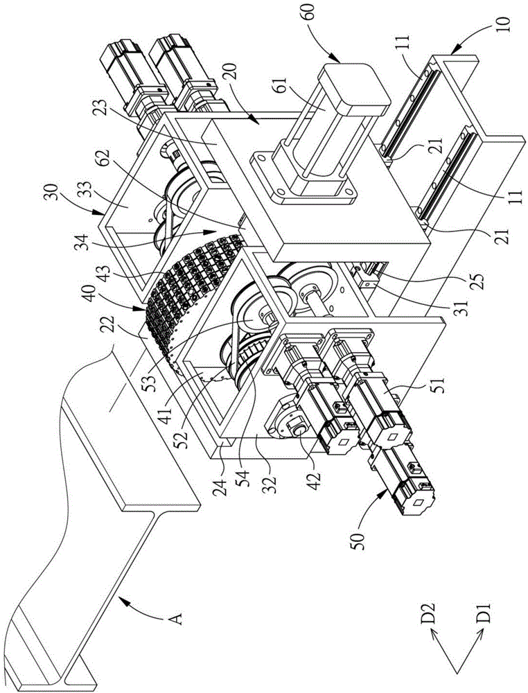
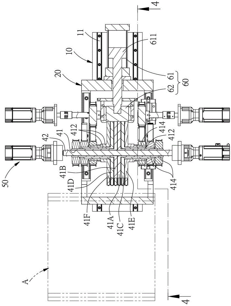
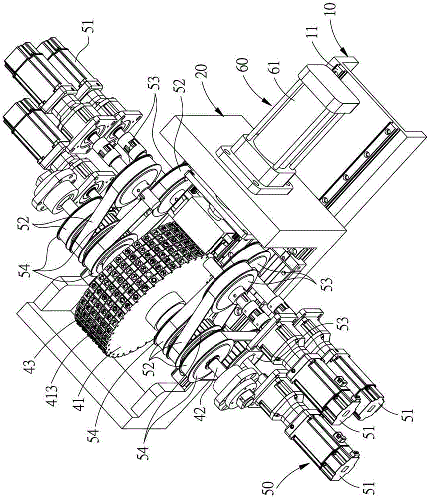
[0040] A preferred embodiment of the marking and printing device for metal workpieces of the present invention is as follows Figure 1 to Figure 5 shown, including:

[0041] A base 10 has a plurality of base slide rails 11 , each of the base slide rails 11 extends along a first direction D1 , and defines a second direction D2 perpendicular to the first direction D1 .

[0042] A device seat 20 is slidably covered on each of the base slide rails 11 with a plurality of device seat sliders 21, so that the device seat 20 can slide on the base 10, and the device seat 20 has Opposed to a workpiece contact surface 22 and a side surface 23, and the two ends of the workpiece contact surface 22 are respectively formed with a step 24, and a plurality of devices are further arranged between the workpiece contact surface 22 and the side surface 23 of the device seat 20. The seat slide rails 25 , each of the device seat slide rails 25 is extended along the first direction D1.

[0043] A sl...


PUM


Abstract

The invention provides a metal workpiece mark printing device; a device base is pivotally provided with printing roller trains having a plurality of cases; all printing roller trains are sleeved on a support mandrel; each case is respectively driven by a drive source so as to change printing portion typefaces needing printing, thus greatly improving typeface changing efficiency, and greatly improving usage convenience; the printing device uses an impressing unit to form marks through an impressing mode, and the marks are clear and hard to erase, thus improving following construction accuracy and convenience.

Description

technical field [0001] The invention relates to a metal workpiece mark printing device, which is related to a device for printing on metal. Background technique [0002] With the development of technology and the diversification of needs, construction methods are no longer limited to traditional mud brick buildings, and steel structures with fast construction and sufficient building strength can be seen everywhere; and the main material of steel structures is through steel As the main building core, after the general steel is cut to the required size, identifiable markings must be made on the steel surface, so that the correct assembly can be carried out corresponding to the markings on the design drawings during the assembly process. [0003] However, the general way of marking on the surface of steel is to mark directly on the surface of steel with paint or ink. However, general steel needs to be galvanized and anti-rust on the surface before assembly, that is, the steel m...

Claims


Application Information

Patent Timeline
IPC IPC(8): B41K3/12B41K3/62
Inventor 余敏守
Owner 余敏守
Learn More