Valve element assembly and stop valve

A technology of spool components and stop valves, which is applied in the direction of lift valves, safety valves, balance valves, etc., can solve the problems of substandard sealing surface sealing performance, shortened service life, and affecting sealing effect, etc., and achieve simple structure and extended service life , long life effect

Inactive Publication Date: 2016-07-06
JIANGSU SHUANGHU ENVIRONMENTAL PROTECTION ENERGY SAVING EQUIP TECH CO LTD
View PDF10 Cites 4 Cited by
  • Summary
  • Abstract
  • Description
  • Claims
  • Application Information

AI Technical Summary

Problems solved by technology

That is to say, with such a sealing surface structure, the sealing performance of the sealing surface is likely to be substandard, and the medium in the valve body flows out from the gap of the sealing surface. If the sealing performance is to be strong, the machining accuracy requirements are relatively high. The sealing part and the disc sealing part are matched with high precision, and the process is complicated
Moreover, the i

Method used


Image

  • Valve element assembly and stop valve
  • Valve element assembly and stop valve
  • Valve element assembly and stop valve

Examples


Embodiment 1

[0055] (Example 1, spool assembly)

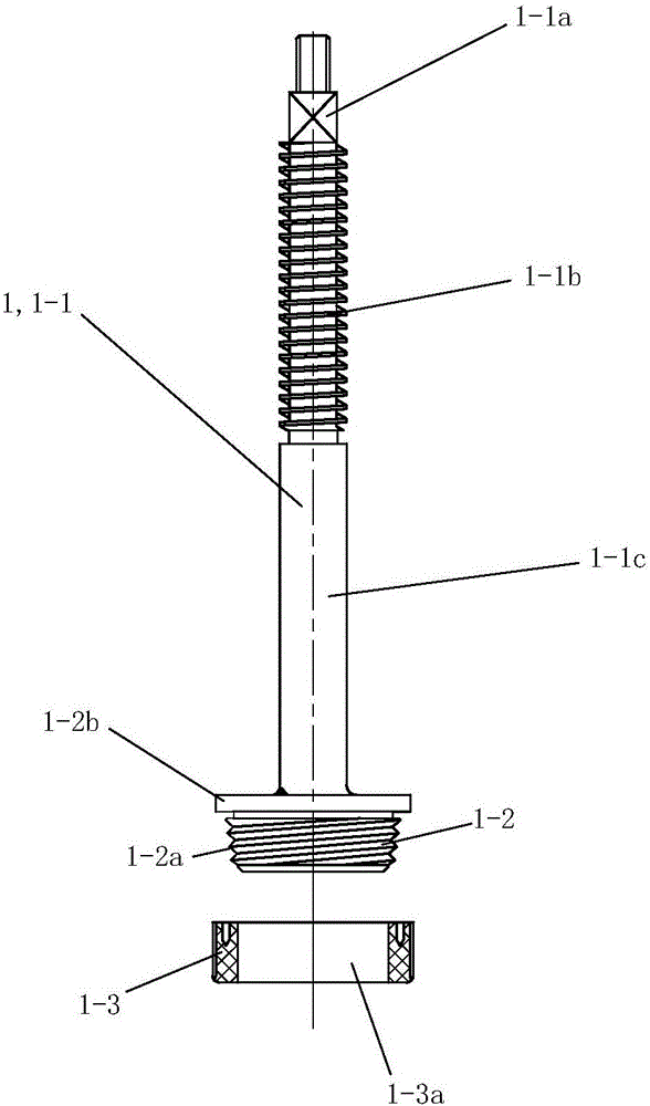
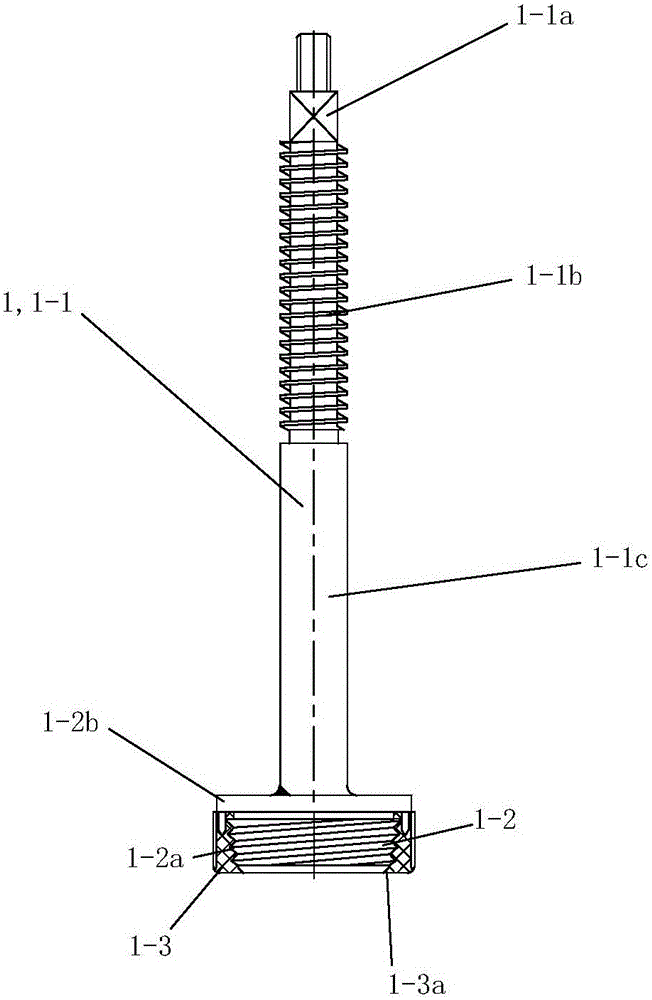
[0056] See figure 1 with figure 2 , The valve core assembly 1 of the present invention includes a valve stem 1-1, a valve flap 1-2 and a sealing packing 1-3.

[0057] See figure 1 with figure 2 The upper end of the valve stem 1-1 is provided with a connecting portion 1-1a, and the connecting portion 1-1a is used for fixed connection with a corresponding handwheel or wrench, so that the rotation of the valve stem 1-1 is controlled by the handwheel or wrench. An external thread section 1-1b is provided on the valve stem 1-1, and the external thread section 1-1b is located below the connecting portion 1-1a, and the length of the external thread section 1-1b can be determined according to actual needs. The lower part of the valve stem 1-1 is a cylindrical sealing connection part 1-1c. The valve clack 1-2 is coaxially fixedly connected and arranged on the lower end of the valve stem 1-1. Conical threads 1-2a are distributed on the outer ...

Embodiment 2

[0060] (Example 2, globe valve)

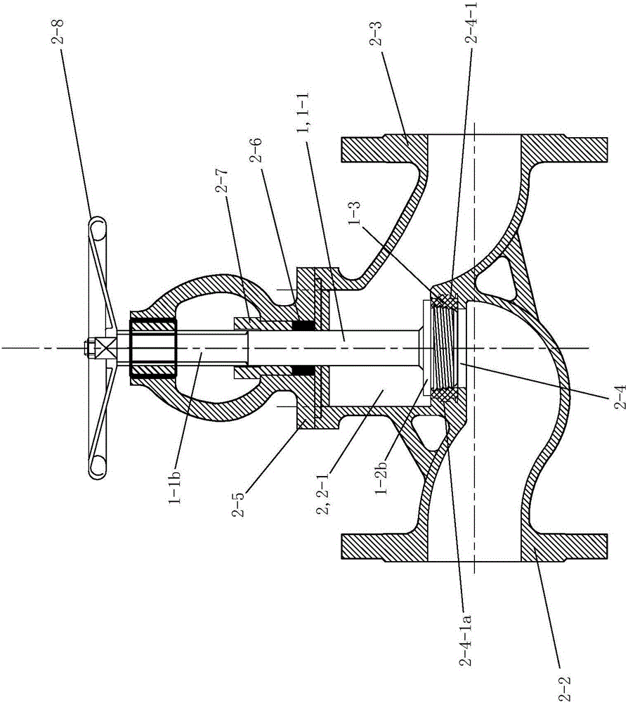
[0061] Such as image 3 , the shut-off valve 2 of this embodiment includes a valve core assembly, and the valve core assembly adopts the valve core assembly 1 described in Embodiment 1. The rest of the stop valve 2 includes: a valve chamber 2-1, the side wall of the valve chamber 2-1 is symmetrically provided with an inlet joint 2-2 and an outlet joint 2-3; the outlet 2-4 of the inlet joint 2-2 extends to The valve cavity 2-1 is set upwards; the outlet 2-4 of the inlet joint 2-2 is provided with an assembly groove 2-4-1, and the assembly groove 2-4-1 is provided with an internal thread. The sealing packing part 1-3 of the valve core assembly 1 is screwed and fixedly arranged in the assembly groove 2-4-1, and the inner wall of the assembly groove 2-4-1 is provided with a groove 2-4- 1a. When the valve disc 1-2 is screwed on the sealing packing part 1-3 for the first time, the taper thread 1-2a of the valve disc 1-2 generates a corresponding ...

Embodiment 3

[0063] (Example 3, cut-off valve)

[0064] Such as Figure 4 , the cut-off valve in this embodiment is the angle cut-off valve 3, and the angle cut-off valve 3 includes a valve core assembly, and the valve core assembly adopts the valve core assembly 1 described in Embodiment 1. The rest of the angle cut-off valve 3 includes: a second valve chamber 3-1, and a second inlet joint 3-2 and a second outlet joint 3 are respectively provided on the adjacent side walls perpendicular to each other of the second valve chamber 3-1. -3; the axis of the second inlet joint 3-2 is set coaxially with the valve stem 1-1 of the valve core assembly 1 . The outlet 3-4 of the second inlet joint 3-2 extends into the second valve chamber 3-1 and is set upward; the outlet 3-4 of the second inlet joint 3-2 is provided with a second assembly groove 3-4- 1. The second assembly groove 3-4-1 is provided with an internal thread, and the sealing packing part 1-3 of the valve core assembly 1 described in E...


PUM


Abstract

The invention discloses a valve element assembly and a stop valve. The valve element assembly is characterized by comprising a valve rod, a valve clack and a sealing filler piece; the valve clack is coaxially and fixedly connected to the lower end of the valve rod; taper threads are distributed on the outer circumferential wall of the valve clack; a center through hole is formed in the sealing filler piece; and the sealing filler piece is made of plastic, and during using, a corresponding inner thread matched with the taper threads is generated in the center through hole of the sealing filler piece through the taper threads of the valve clack. After the valve element assembly is adopted in the stop valve, the stop valve is simple in structure and convenient to use, during using, only the sealing filler piece needs to be fixed in an installing groove of the stop valve firstly, the inner thread on the sealing filler piece is generated through the corresponding taper threads of the valve clack, the positioning problem does not need to be considered, and matching is reliable.

Description

technical field [0001] The invention relates to the field of valves, and is particularly applicable to various gas and liquid tanks, especially for high-pressure liquid storage tanks such as chlorine gas and liquefied gas, as well as valve core components and components of vertical or horizontal shut-off valves on high-pressure liquid or gas delivery pipelines. the shut-off valve. Background technique [0002] Globe valve, also called cut-off valve, is one of the most widely used valves. The reason why it is popular is that the friction between the sealing surfaces is small during the opening and closing process, it is relatively durable, the opening height is not large, and it is easy to manufacture. , easy maintenance, not only suitable for medium and low pressure, but also suitable for high pressure. At present, the globe valve usually includes a valve body, a valve disc, and a valve stem for driving the valve disc to move up and down in a straight line. The valve body i...

Claims


Application Information

Patent Timeline
IPC IPC(8): F16K1/02F16K1/48F16K1/32F16K1/36
CPCF16K1/02F16K1/38F16K1/48F16K17/36F16K17/38F16K1/32F16K1/36
Inventor 黄蓉钰邹岳明邹玉杰王雨荍黄清
Owner JIANGSU SHUANGHU ENVIRONMENTAL PROTECTION ENERGY SAVING EQUIP TECH CO LTD
Why Eureka
Try Eureka