Ball valve

A technology for ball valves and bonnets, which is applied to valve details, valve devices, valve shell structures, etc., can solve the problems of ball valves without filtering function, easy to produce gaps, easy to damage valve cores, etc. damage effect

Inactive Publication Date: 2016-07-06
章俊
View PDF6 Cites 0 Cited by
  • Summary
  • Abstract
  • Description
  • Claims
  • Application Information

AI Technical Summary

Problems solved by technology

[0003] At present, the common structure of the ball valve is: including a tubular ball valve body, one side of the inner cavity of the ball valve body is provided with a limit ring, the valve core is installed in the ball valve body, and the other side is fixed to the valve core through the bonnet and the inner cavity of the ball valve body. The limit is fixed. In the existing structure, after the bonnet and the ball valve body are fixed, the bonnet extends out of the ball valve body or is flush with the end surface of the ball valve body. When the ball valve is used for a long time or the temperature changes alternately, the distance between the outer wall of the bonnet and the inner wall of the ball valve The connection between them is easy to produce gaps, resulting in dripping
Moreover, the existing ball valve does not have a filtering function, and the valve core is easily damaged

Method used


Image

  • Ball valve
  • Ball valve
  • Ball valve

Examples


Embodiment Construction

[0023] The present invention will be described in further detail below in conjunction with the accompanying drawings.

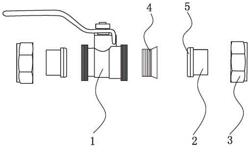
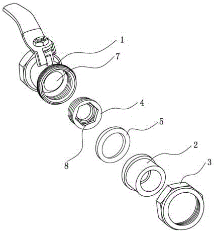
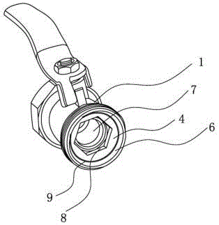
[0024] Such as figure 1 —3: A ball valve, including a ball valve main body 1, two tubular plastic connectors 2 and two fixing nuts 3, the inner cavity of the ball valve main body 1 is provided with a ball valve core 7, and the connectors pass through the fixing nuts. The caps are fixed on both ends of the ball valve body 1. The inner cavity of the ball valve body 1 is provided with a bonnet 4 located on one side of the ball valve core and fixing the ball valve core. The outside of the valve cap and the inside of the ball valve body 1 The walls are fixedly connected, and the rear end of the connector is provided with a sealing ring 5 that is tightly pressed at the gap 9 between the bonnet and the ball valve body 1 for sealing.

[0025] The present invention is a PPR double live ball valve, and the above-mentioned plastic connecting head 2 is made of material....


PUM


Abstract

The invention discloses a ball valve, which comprises a ball valve main body, two tubular plastic connectors and two fixing nuts. The inner cavity of the ball valve main body is provided with a ball valve core, and the connectors are fixed on the ball valve main body through the fixing nuts. The inner cavity of the ball valve body is provided with a bonnet located on one side of the ball valve core and fixing the ball valve core. The outside of the bonnet is fixedly connected with the inner wall of the ball valve body. The connection The rear end of the head is provided with a sealing ring that is tightly pressed on the gap between the bonnet and the ball valve body for sealing. The invention has the advantages of simple structure, convenient installation, stable and reliable interface, no seams on the surface of the ball valve, avoiding dripping phenomenon, and the valve core is not easily damaged.

Description

technical field [0001] The invention relates to a valve, specifically a ball valve, and belongs to the technical field of valves. Background technique [0002] Double union ball valve is more common in the market. Its structure is simple. The connecting pipes at both ends are made of PPR material, and the middle is a metal ball valve. It can be used for pipeline repair and pipeline connection, and is easy to operate. [0003] At present, the common structure of the ball valve is: including a tubular ball valve body, one side of the inner cavity of the ball valve body is provided with a limit ring, the valve core is installed in the ball valve body, and the other side is fixed to the valve core through the bonnet and the inner cavity of the ball valve body. The limit is fixed. In the existing structure, after the bonnet and the ball valve body are fixed, the bonnet extends out of the ball valve body or is flush with the end surface of the ball valve body. When the ball valve ...

Claims


Application Information

Patent Timeline
Patent Type & Authority Applications(China)
IPC IPC(8): F16K5/06F16K27/06B01D35/04
CPCF16K5/06B01D35/04F16K27/067
Inventor 章俊
Owner 章俊
Why Eureka
Try Eureka